Heat Shrink Cable Accessory Kits
C15 Medium Voltage Heat Shrink Cable Accessory Kits 8.7/15 kV
Indoor outdoor and joint kits for 8.7/15 (17.5) kV single core and three core cable tested to IEC 60502-4
- Voltage class: 8.7/15 (17.5) kV
- Operating temperature: -55°C to 105°C
- Supplied by set, with the materials in the kit
- Well resistance against weather and damage
- Compliant Standard: IEC 60502-4: 2010-12, GB/T 12706.4
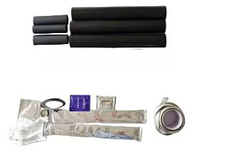
C15 · Cable Accessory Kits
Product Overview
What C15 Does
Single core, 3 cores cable accessories. Suitable for protection of indoor and outdoor electric power cable joint and termination up to 8.7/15 (17.5) kV.
Indoor outdoor and joint kits for 8.7/15 (17.5) kV single core and three core cable tested to IEC 60502-4 It is manufactured by Dalian United Polymer Material Co., Ltd. in Dalian China where radiation cross linking extrusion and molding are all performed in house under one quality system.
Key Benefits
- An accessory family that satisfies both IEC 60502-4 and GB/T 12706.4 in one submission
- Indoor outdoor and joint variants that share the same installation method so crews train once
- Partial discharge held to 10 pC maximum at ambient and at operating temperature
- 1000 hours of salt fog at 1.25 U0 for the outdoor variant so coastal sites stay in service
- Complete kit including stress control non tracking insulation screen continuity and sealing
Who It Is For
Who Benefits Most from C15
The buyers and site teams this product was designed around
Distribution Utilities
Ring main units substation feeders and 11 kV or 15 kV overhead to underground transitions where an approved accessory is a licence condition.
EPC Contractors on Grid Projects
Bulk purchase of a single accessory family across a whole substation or feeder replacement programme.
Industrial Plant Maintenance Teams
Steel plants cement works refineries and mines that hold their own MV spares and joint their own cable during shutdowns.
Renewable Collector Networks
Wind farm and utility solar collector circuits at 15 kV class where accessories are installed in the field far from a workshop.
Problems It Solves
Problems This Product Removes
Every one of these is a failure mode we have seen on real networks
Field Stress at the Screen Cut Back Causes Early Failure
Cutting the metallic screen creates a sharp electrical discontinuity. The C15 kit includes a stress control layer that redistributes that field so partial discharge stays inside the 10 pC limit.
Type Test Evidence Is Demanded Before Approval
Utilities will not accept an accessory without a full IEC 60502-4 test record. C15 is designed against the complete test sequence including impulse heating cycles thermal short circuit humidity and salt fog.
Outdoor Terminations Flash over in Polluted Air
Salt coastal air cement dust and industrial pollution build a conducting film. The outdoor WSY variant uses non tracking material plus rain sheds to lengthen the creepage path.
Joints Under Water Fail at the Interface
Duct and manhole joints sit in water for years. The C15 joint is tested for 30 heating cycles under 1 m of water at 2.5 U0 with no breakdown.
Application Scenarios
Where It Is Used
Ring Main Unit Terminations
Three core 15 kV XLPE entering an RMU where space is tight and the termination must be short.
Overhead to Underground Transitions
Outdoor pole terminations exposed to UV rain and airborne pollution.
Straight Through Joints in Manholes
Feeder joints in flooded chambers that must survive continuous immersion.
Substation Transformer Tails
Single core terminations into a transformer cable box with defined phase spacing.
Wind Farm Collector Circuits
Tower base and switching station terminations at 15 kV class in remote locations.
Technical Data
Specifications and Dimensions
Test methods and requirements taken directly from the manufacturing specification
Test Procedures and Requirements for Heat-Shrinkable Terminations
| No. | Test | Condition | Requirements | Test Sequence 1.1 | 1.2 | 1.3 | 1.4 | 1.5 |
|---|---|---|---|---|---|---|---|---|
| 1 | AC and DC Voltage | 4.5 U0, 5min (AC) and 4.0 U0, 15min (DC) | No breakdown, No flashover | X | X | X | ||
| 2 | AC (wet,indoor) | 4.0 U0, 1min | No breakdown, No flashover | X | ||||
| 3 | Partial discharge | At 1.73 U0 (ambient temperature) | 10 pC max. | X | ||||
| 4 | Impulse at θt | 10 impulses of each polarity | No breakdown, No flashover | X | ||||
| 5 | Heating cycles in air (indoor) | 60 cylces at θt and 2.5 U0 | No breakdown, No flashover | X | ||||
| 6 | Immersion test (outdoor) | 10 cylces at θt (IEC 61442: 2005 9.4) | / | X | ||||
| 7 | Partial discharge | At 1.73 U0 (at θt and ambient temperature) | 10 pC max. | X | X | |||
| 8 | Thermal short-circuit (screen) | two short-circuits at Isc of the cable screen | No visible deterioration | X | X | |||
| 9 | Thermal short-circuit (conductor) | two short-tircuits to raise conductor to θsc of the cable | No visible deterioration | X | X | |||
| 10 | Dynamic short-circuit | One short-circuit at Id | No visible deterioration | X | ||||
| 11 | Impulse (ambient temperature) | 10 impulses of each polarty | No breakdown, No flashover | X | X | X | ||
| 12 | AC voltage | 2.5 U0, 15min | No breakdown, No flashover | X | X | X | ||
| 13 | Humidity (Indoor) | 300 hrs at 1.25 U0, tripping times not more than three | No breakdown or flashover, no significant damage. | X | ||||
| 14 | Salt fog (Outdoor) | 1000 hrs at 1.25 U0, tripping times not more than three | No breakdown or flashover, no significant damage. | X | ||||
| 15 | Examination | For information only | GB/T 12706.4 IEC 60502-4 | X | X | X | X | X |
Test Procedures and Requirements for Heat-Shrinkable Joint
| No. | Test | Condition | Requirements | Test Sequence 2.1 | 2.2 | 2.3 |
|---|---|---|---|---|---|---|
| 1 | AC and DC Voltage | 4.5 U0, 5min (AC) and 4.0 U0, 15min (DC) | No breakdown, No flashover | X | X | X |
| 2 | Partial discharge | At 1.73 U0 (ambient temperature) | 10 pC max. | X | ||
| 3 | Impulse at θt | 10 impulses of each polarity | No breakdown, No flashover | X | ||
| 4 | Heating cycles in air | 30 cylces at θt and 2.5 U0 | No breakdown, No flashover | X | ||
| 5 | Heating cycles in air (under water) | 30 cylces at θt and 2.5 U0, water heitht 1m | No breakdown, No flashover | X | ||
| 6 | Partial discharge | At 1.73 U0 (at θt and ambient temperature) | 10 pC max. | X | ||
| 7 | Thermal short-circuit (screen) | two short-circuits at Isc of the cable screen | No visible deterioration | X | X | |
| 8 | Thermal short-circuit (conductor) | two short-tircuits to raise conductor to θsc of the cable | No visible deterioration | X | X | |
| 9 | Dynamic short-circuit | One short-circuit at Id | No visible deterioration | X | ||
| 10 | Impulse (ambient temperature) | 10 impulses of each polarty | No breakdown, No flashover | X | X | X |
| 11 | AC Voltage | 2.5 U0, 15min | No breakdown, No flashover | X | X | X |
| 12 | Examination | For information only | GB/T 12706.4 IEC 60502-4 | X | X | X |
8.7/15 (17.5) kV Selection
| Size of conductor (mm2) 25-50 | Cable core number 3 | Product description NSY-1031 | Installation Location Terminations Indoor | |
|---|---|---|---|---|
| 70-120 | 3 | NSY-1032 | Terminations Indoor | |
| 150-240 | 3 | NSY-1033 | Terminations Indoor | |
| 300-400 | 3 | NSY-1034 | Terminations Indoor | |
| 25-50 | 3 | WSY-1031 | Terminations Outdoor | |
| 70-120 | 3 | WSY-1032 | Terminations Outdoor | |
| 150-240 | 3 | WSY-1033 | Terminations Outdoor | |
| 300-400 | 3 | WSY-1034 | Terminations Outdoor | |
| 25-50 | 3 | JSY-1031 | Joint | |
| 70-120 | 3 | JSY-1032 | Joint | |
| 150-240 | 3 | JSY-1033 | Joint | |
| 300-400 | 3 | JSY-1034 | Joint | |
| 25-50 | 1 | NSY-1011 | Terminations Indoor | |
| 70-120 | 1 | NSY-1012 | Terminations Indoor | |
| 150-240 | 1 | NSY-1013 | Terminations Indoor | |
| 300-400 | 1 | NSY-1014 | Terminations Indoor | |
| 25-50 | 1 | WSY-1011 | Terminations Outdoor | |
| 70-120 | 1 | WSY-1012 | Terminations Outdoor | |
| 150-240 | 1 | WSY-1013 | Terminations Outdoor | |
| 300-400 | 1 | WSY-1014 | Terminations Outdoor | |
| 25-50 | 1 | JSY-1011 | Joint | |
| 70-120 | 1 | JSY-1012 | Joint | |
| 150-240 | 1 | JSY-1013 | Joint | |
| 300-400 | 1 | JSY-1014 | Joint |
Manufacturing and Quality
How It Is Made and Checked
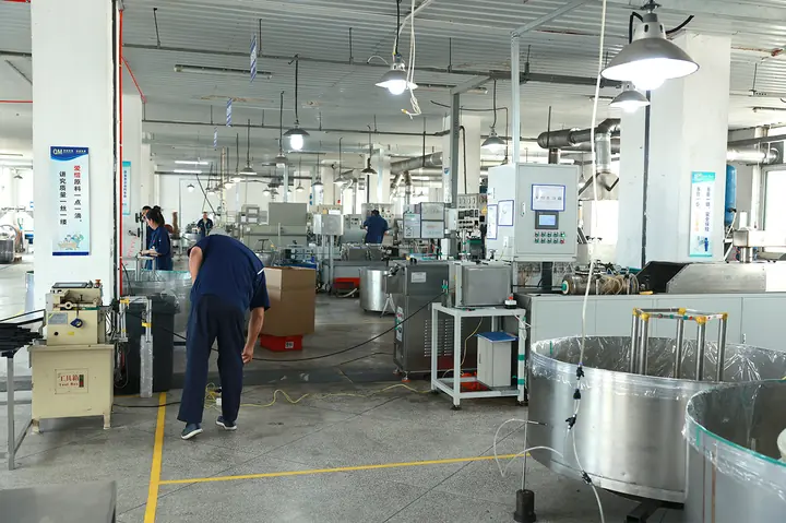
Compounding extrusion radiation cross linking expansion and test all under one roof in Dalian
-
01
Compounding
Base polyolefin antioxidants flame retardants and functional fillers are mixed to a recipe held under our own formulation control rather than bought as a masterbatch.
-
02
Extrusion
The compound is extruded to the required wall and diameter. Co extruded products form two or three layers in a single pass so no interface can trap air.
-
03
Radiation Cross Linking
Electron beam irradiation creates the cross linked network that gives the material its shape memory. This step is what makes the product heat shrinkable.
-
04
Expansion
The cross linked part is heated expanded to its supplied diameter and cooled under tension so the expanded shape is locked in until heat is applied again.
-
05
Test and Inspection
More than 90 percent of product performance tests are carried out in our own laboratory including tensile elongation heat aging dielectric strength and tracking resistance.
-
06
Packing and Traceability
Each batch carries a production record so a delivered part can be traced back to its compound lot and process parameters.
Certification
ISO 9001:2015
Quality management system
IATF 16949:2016
Automotive quality management
ISO 14001:2015
Environmental management
ISO 45001:2018
Occupational health and safety
GJB 9001C-2017
Defence quality management
UL 224 E341796
Extruded insulating tubing
CE / RoHS
European conformity and restricted substances
CCS / ABS / DNV
Marine classification society approvals
Comparison
How C15 Compares
An honest comparison so you can rule this product in or out quickly
| Accessory Type | Where It Is Used | Creepage Strategy | Relative Cost |
|---|---|---|---|
| C15 NSY indoor termination | Switchgear cable box RMU panel | Non tracking tube only | Lowest |
| C15 WSY outdoor termination | Pole top open air substation | Non tracking tube plus rain sheds | Medium |
| C15 JSY joint | Duct manhole direct buried | Sealed with semiconductive screen restored | Medium |
| Cold shrink termination | Same positions | Silicone rubber body | Highest |
Use Guide
How to Select and Install C15
The sequence our engineers walk customers through on every first installation
-
01
Match Voltage Class First
C15 is for 8.7/15 (17.5) kV. Do not fit it on a 26/35 kV circuit. Use C35 above 15 kV class.
-
02
Choose Indoor Outdoor or Joint
NSY is an indoor termination WSY is an outdoor termination and JSY is a joint. The choice sets whether rain sheds are included.
-
03
Read the Conductor Band
Bands are 25 to 50 70 to 120 150 to 240 and 300 to 400 mm². The last digit of the part number is the band.
-
04
Prepare and Clean
Remove outer sheath armour and semiconductive screen to the dimensions in the kit drawing. Every trace of semiconductive material must be cleaned off the insulation.
-
05
Apply Stress Control
Fit the stress control tube over the screen cut back so it overlaps both the screen and the insulation by the stated distance.
-
06
Insulate Seal and Screen
Apply the non tracking insulating tubes then restore screen continuity with the supplied braid and constant force spring then seal the ends with adhesive lined tubing.
-
07
Add Rain Sheds Outdoors
Fit the supplied Y3 sheds at even spacing to build the creepage distance the site pollution level requires.
FAQ
C15 Frequently Asked Questions
The questions buyers ask before they place an order
Does C15 comply with IEC 60502-4
What is the difference between NSY WSY and JSY
Can I use C15 on an 11 kV network
How much partial discharge does the design allow
Is a screen continuity braid included
How should kits be stored before use
Do you supply private label kits
Still need an answer ask our engineers on WhatsApp
Related
Related Products
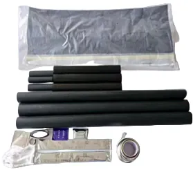
MV Kits 26/35 kV
The highest voltage class in the range covering 26/35 (40.5) kV single core and three core cable to 630 mm²
VIEW DETAILS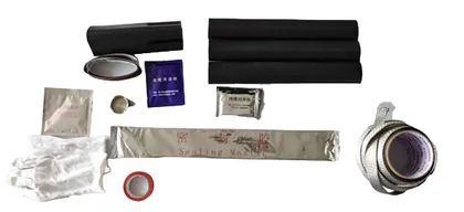
LV Kits 0.6/1 kV
Complete 1 kV termination and joint kits for 1 to 6 core cable from 4 mm² to 400 mm² supplied as a single part number
VIEW DETAILS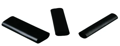
C102-10 Stress Control
High permittivity black tubing that redistributes the electrical field at the screen cut back on 6 to 24 kV cable
VIEW DETAILS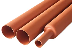
C101 Non Tracking Tube
Red anti tracking outer insulation for indoor and outdoor terminations and joints from 6 kV to 36 kV
VIEW DETAILS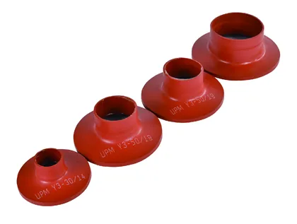
Y3 Rain Sheds
Red anti tracking skirts with mastic collars that build creepage distance on outdoor terminations from 1 kV to 36 kV
VIEW DETAILSGet a Quotation for C15
Send us the voltage class conductor size and quantity and we will return a part number a price and a lead time. No form to fill in.