
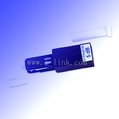
MU Attenuator
MU Attenuator is part of the fiber optic attenuator range built by Ever Expresslink Limited in Ningbo, China. It is built on the MU (Miniature Unit) interface.
Controlled loss, for when a receiver is being overdriven
Interested in MU Attenuator
Email the model and quantity with your destination country. We reply with pricing, lead time and a datasheet.
Product Overview
MU Attenuator is part of the fiber optic attenuator range built by Ever Expresslink Limited in Ningbo, China. It is built on the MU (Miniature Unit) interface.
We supply both UPC MU fiber optic attenuator and APC MU fiber optic attenuators for single mode applications. Their attenuation level ranges from 1dB to 30dB. This MU fiber attenuator can work at 1240nm to 1620nm range, including the typical SMF 1310nm and SMF1550nm. Our MU fiber optic attenuators feature the high return loss, high power light source durability and wavelength independence. They are suit to use with EDFA, DWDM and other fiber optic communication systems to reduce the optical light power at a fixed level. The MU fiber attenuators are good price and prompt delivery.
MU is a 1.25 mm ferrule connector with a push-pull body, effectively a miniaturised SC. It appears in high-density telecom shelves and in optical device packaging where a full-size SC footprint will not fit.
Key Benefits
- Supplied as MU Attenuator, so the part you receive matches the designation you ordered against
- Fixed values for production use and tunable versions for the bench
- Male-to-female plug styles that drop straight into an existing port
- Available across the main connector types and both polish styles
- Low back-reflection versions for return-loss-sensitive paths
Problems It Solves
- Commissioning delays while power levels are brought into range
- Ad-hoc attenuation methods that drift with temperature
- Receiver saturation on short links built with high-power transmitters
- Bit errors that look like contamination but are actually overload
Application Scenarios
- Optical component packaging
- Balancing levels across a CATV optical distribution network
- Characterising receiver sensitivity on a test bench
- Simulating span loss during equipment qualification
- Correcting an over-powered PON path at the splitter output
Who It Is For
- Test laboratories characterizing receivers
- CATV and RF-over-glass operators balancing distribution levels
- Maintenance teams diagnosing overload symptoms
- Commissioning engineers bringing links into their power window
Technical Features
- MU (Miniature Unit) interface
- MU parts are not interchangeable with LC despite the shared 1.25 mm ferrule size. Confirm the housing standard, not just the ferrule diameter.
- Fixed attenuation values across the common dB steps
- Tunable versions with a continuously adjustable range
- MEMS variable versions for programmable bench work
- Male-to-female plug style for direct insertion into a port
Materials
- Doped fiber or coated-ferrule attenuating element
- Zirconia ceramic ferrule
- Metal or thermoplastic housing
- Precision adjustment mechanism on tunable versions
Specifications
| Product Designation | MU attenuator |
|---|---|
| Product Family | Fiber Optic Attenuator |
| Connector Interface | MU (Miniature Unit) |
| Manufactured In | Ningbo, China |
| Warranty | One year against defects in materials and workmanship |
Values shown are those carried by the product designation. Dimensional and optical values for a specific order are confirmed on the quotation.
Manufacturing Process
- Attenuating element preparation to the target value
- Connector assembly and polish
- Attenuation calibration against a reference
- Return loss verification
- Marking, capping and packing
Quality Control
- Attenuation value verified per unit against a calibrated reference
- Return loss measured on every unit
- Wavelength response checked on sample units
- Temperature stability sampled per production lot
- Marking accuracy checked against the measured value
Customization Options
- Attenuation value to your specification
- Fixed, tunable or MEMS variable format
- Connector type and polish
- Low back-reflection versions
- Matched sets for multi-channel balancing
Compared With Other Options
| LC | Both use a 1.25 mm ferrule; LC has far wider transceiver support, MU appears mainly in telecom equipment |
|---|---|
| SC | MU is the compact equivalent of SC where panel space is the binding constraint |
Handling MU Attenuator
Before You Order
- Measure the actual received power before choosing a value
- Choose the value that lands mid-window, not at the edge of the receiver range
- Install on the receive side rather than the transmit side
In Service
- Use APC versions on paths where return loss is critical
- Re-measure after installation to confirm the link is inside its window
- Record the installed value in the link documentation
Questions About MU Attenuator
What do you need from us to quote MU Attenuator?
The quantity, the destination and anything that has to match on your side: connector and polish at each end, fiber mode and core size, and length where the item is an assembly. If you are matching a part you already buy, send the sample and we will quote against it.
Can MU Attenuator be supplied with a different connector interface?
Yes. MU (Miniature Unit) is what this designation carries, and the same family is stocked across the other mainstream connector standards. Tell us the port you have to mate with and we will confirm the equivalent part.
Can an attenuator fix errors caused by a dirty connector?
No, and the two are easy to confuse. Clean and inspect first. Only when power is genuinely above the receiver's maximum input is an attenuator the right answer.
How do I choose the right attenuation value?
Measure the received power with a power meter, compare it against the receiver's specified input range, and pick the value that puts you near the middle of that range rather than at its edge.
Where should the attenuator go, transmit or receive side?
The receive side. Attenuating at the transmitter reduces the margin available for the span itself, whereas attenuating at the receiver directly addresses the overload.
More Fiber Optic Attenuator
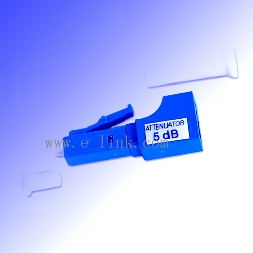
LC Attenuator
We supply single mode LC fiber optic attenuators including the bulkhead LC attenuator and female to male LC fiber attenuator.
View Details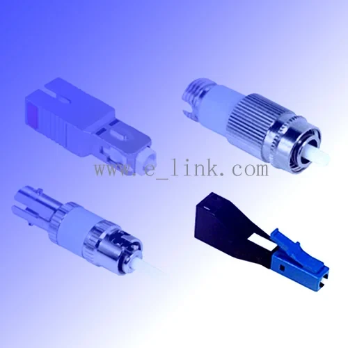
Attenuator
Sometimes in the fiber optic network, people may need to reduce or balance the power of the light transmitted from one device to another device, fiber optic.
View Details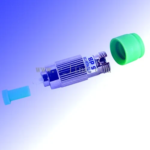
FC Attenuator
We supply FC APC single mode fiber optic attenuator and FC UPC single mode fiber optic attenuator, both of them are with ceramic sleeves and accurate FC connection.
View Details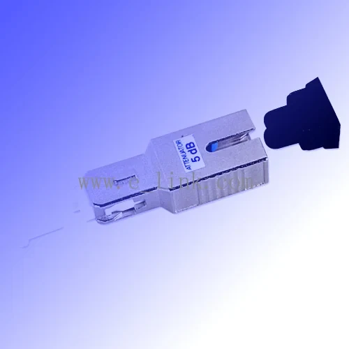
SC Attenuator
We supply female to male SC fiber optic attenuator and bulkhead SC fiber optic attenuator.
View DetailsGuides Cases and Industries
PLC and FBT Optical Splitters Compared
Two ways to divide light, why PON standardized on one of them, and how to check whether your budget can carry the split you want.
Buying GuideHow to Select a Fiber Optic Attenuator
Measure first, attenuate on the receive side, and record what you installed. The three rules that prevent most attenuator mistakes.
Process GuideInsertion Loss and Return Loss Explained
Two numbers on every test report, what each one is telling you, and how to build a link budget that survives being maintained.
Deployment ProfileCATV Optical Level Balancing
Bringing an optical distribution tree into level, and keeping reflections out of the picture
IndustryCATV and Broadcast Networks
Optical and coaxial distribution where return loss and level balance decide picture quality
IndustryTest Measurement and OEM Integration
Component-level supply for instrument builders and cable assembly houses
Request Pricing For MU Attenuator
Tell us the quantity and destination. If you are matching a part you already buy, send the sample and we will quote against it.