
CATV and Broadcast Networks
Optical and coaxial distribution where return loss and level balance decide picture quality
What Makes This Sector Different
On an RF-over-glass or coaxial distribution network the failure mode is not a dead link, it is a degraded one. Reflections and level imbalance show up as picture artifacts long before anything stops working, which makes end-face polish and attenuation planning part of the video quality chain.
Pain Points
- Back reflection from UPC end faces degrading an RF-over-glass path
- Output levels drifting across a distribution tree after additions
- 50 and 75 ohm parts mixed on one video path
- Optical and coaxial plant sourced from unrelated suppliers
- Attenuation improvised rather than specified
What Buyers Need
- APC polish across the optical distribution path
- Calibrated fixed attenuators for level balancing
- Impedance-consistent coaxial connectors and feeder
- Optical splitters with measured uniformity across ports
- One supplier covering both the optical and the coaxial side
Typical Applications
- Optical distribution from a headend to node equipment
- Balancing levels across a distribution tree
- Coaxial distribution inside a building or a block
- Feeding several outputs from one source through RF splitters
- Replacing corroded outdoor coaxial connections
Ranges We Supply Into CATV and Broadcast Networks
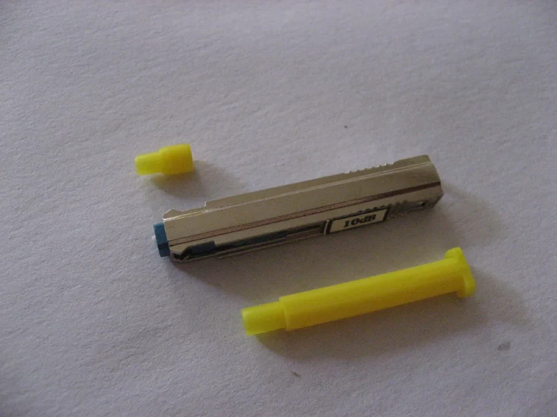
Fiber Optic Attenuator
Controlled loss, for when a receiver is being overdriven
10 products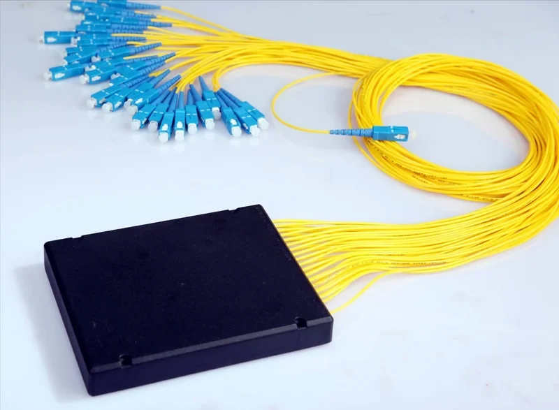
Fiber Optic Splitter
Passive power division, the component PON architecture is built on
6 products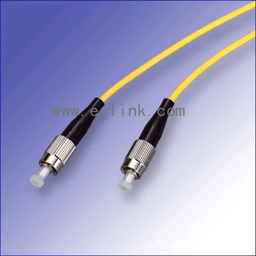
Fiber Optic Patchcord
Factory-terminated jumpers that turn a planned link budget into a working one
11 products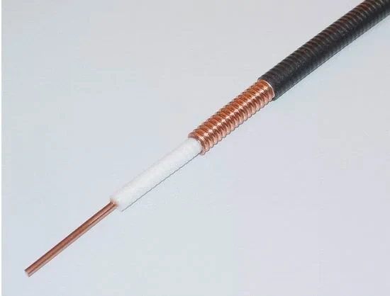
Coaxial Cable
Feeder and data cable for RF distribution and structured copper runs
3 products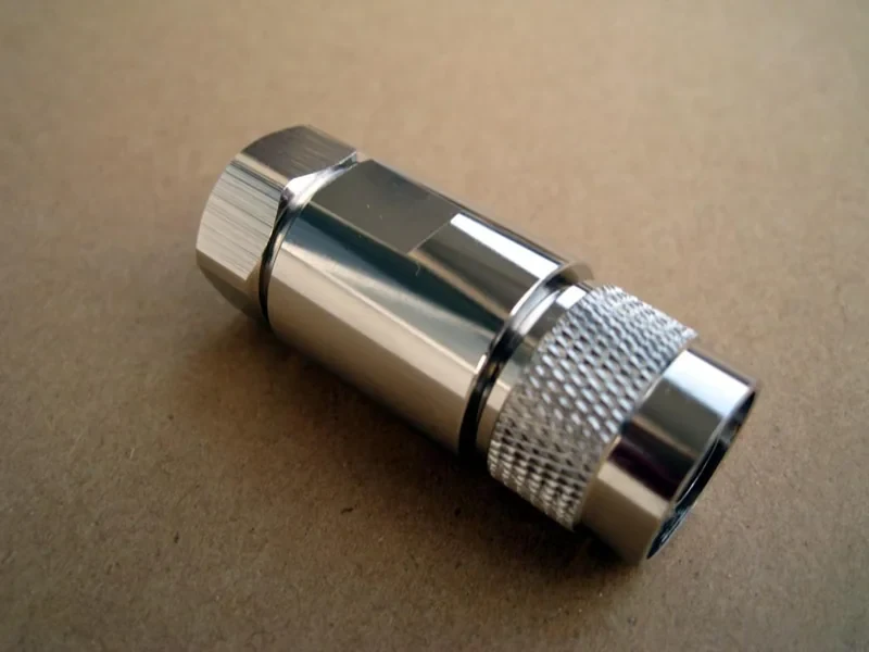
Coaxial Connector
Feeder and instrument connectors that keep impedance continuous
4 products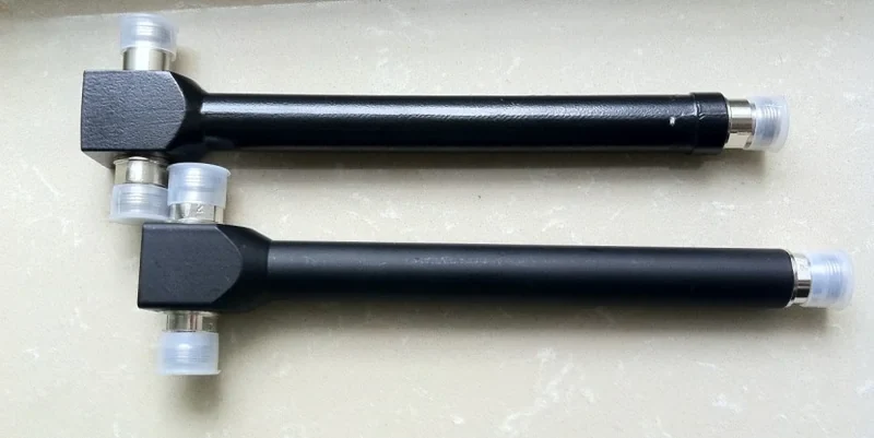
Splitter
RF signal division for antenna and distribution systems
2 products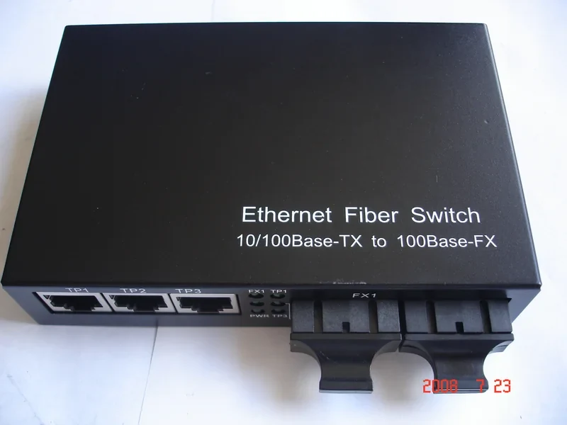
Fiber Optic Media Converter
Copper to fiber conversion where distance or interference rules out twisted pair
8 products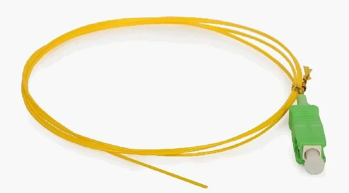
Various Pigtail
Pre-terminated tails that put the factory end face inside your splice tray
12 productsFrom Specification To Repeat Supply
We work from your source level and distribution tree so attenuator values and split ratios are specified rather than guessed.
APC optical parts and impedance-matched coaxial parts are selected together for the same path.
Samples are supplied with measured values before volume is committed.
Attenuators are calibrated per unit and splitters tested on every port.
Measured values can accompany the shipment for your commissioning records.
Delivery Capability
- Attenuators calibrated and marked per unit
- Splitter uniformity measured across all ports
- APC polish across the optical path
- Matched coaxial cable and connector supply
- One-year warranty against defects in materials and workmanship
Related Solutions
- FTTH Network Rollout Supply
- Consolidated Sourcing and Export
How The Parts Go Together
CATV and Broadcast Networks Questions
Why does APC matter so much on an RF-over-glass path?
Because reflected light interferes with the modulated signal and shows up as picture degradation. An angled end face throws the reflection into the cladding instead of back down the core, which is why APC is standard on these paths.
Can you supply attenuators at specific calibrated values?
Yes. Attenuation is calibrated per unit against a reference and marked accordingly. Tell us the values your level plan needs.
Do you supply both the optical and the coaxial side?
Yes, both are in the same catalog and can go on one order, which avoids the impedance and interface mismatches that come from splitting the purchase.
How do we avoid mixing 50 and 75 ohm parts?
Keep the two stocks physically separated and order them as distinct part numbers. The bodies look similar enough that relying on visual identification on site does not work.
Further Reading
UPC and APC End Face Polish Explained
Why an eight degree angle changes where reflected light goes, when that matters enough to pay for it, and what happens if the two are mated.
Buying GuideHow to Select a Fiber Optic Attenuator
Measure first, attenuate on the receive side, and record what you installed. The three rules that prevent most attenuator mistakes.
Process GuideInsertion Loss and Return Loss Explained
Two numbers on every test report, what each one is telling you, and how to build a link budget that survives being maintained.
Supplying CATV and Broadcast Networks
Send us the specification, the architecture or the bill of materials. We will come back with what fits and what it costs.