
Fiber Optic Splitter
Passive power division, the component PON architecture is built on
All 6 Fiber Optic Splitter Products
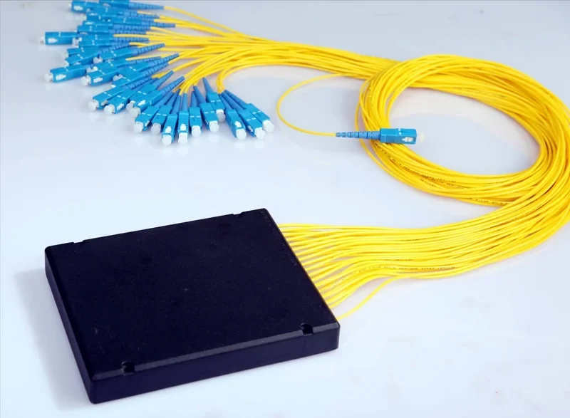
Splitter (Ref 311)
Used for distributing signal inside an FTTH splice closure.
View Details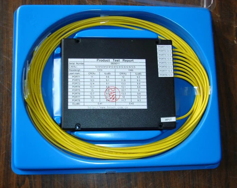
Splitter (Ref 312)
Used for splitting for monitoring and test taps.
View Details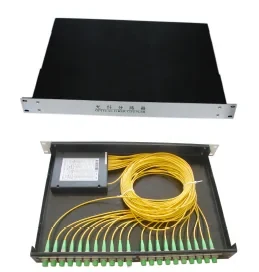
Splitter Enclosure
Used for dividing a PON feeder inside a street cabinet.
View Details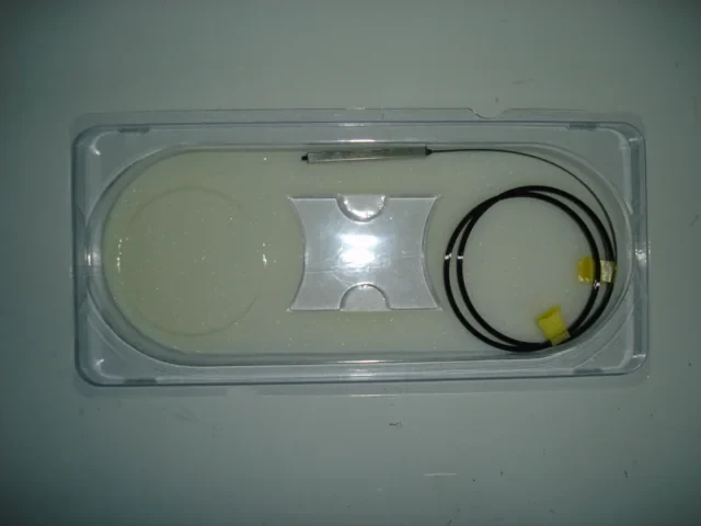
WDM Coupler
Used for optical distribution in a CATV headend.
View Details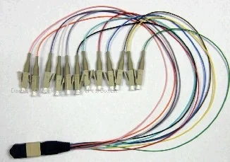
MTP-LC (Ref 297)
Used for dividing a PON feeder inside a street cabinet.
View Details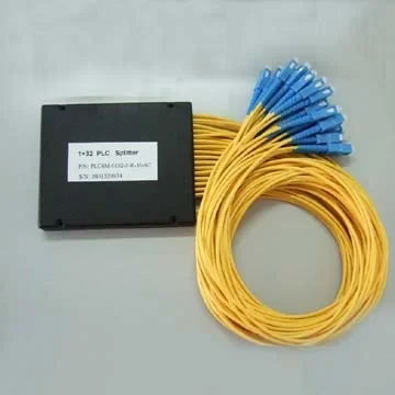
Fiber Splitter
Used for distributing signal inside an FTTH splice closure.
View DetailsFiber Optic Splitter In Practice
A splitter is what makes a passive optical network passive. One feeder fiber from the exchange is divided among many subscribers with no power, no electronics and nothing in the field that can fail electrically. The cost of that is optical budget, which is why split ratio is an architectural decision rather than a purchasing one.
Problems This Range Solves
- Feeder fiber count that would be impossible to justify with point-to-point links
- Split ratios chosen without checking the resulting power budget
- Uniformity variation across outputs that leaves some subscribers marginal
- Enclosure formats that do not fit the cabinet or closure being used
- Reflections from splitter ports degrading upstream performance
Who It Is For
- FTTH and PON network operators
- Access network design teams
- CATV operators distributing optical signal
- Cabinet and closure assemblers
- System integrators building distribution nodes
Where It Is Used
- Dividing a PON feeder inside a street cabinet
- Distributing signal inside an FTTH splice closure
- Rack-mounted splitting inside a central office
- Optical distribution in a CATV headend
- Splitting for monitoring and test taps
What You Get From Our Fiber Optic Splitter
Advantages
- Fully passive, so nothing in the distribution node needs power or cooling
- Consistent uniformity across output ports
- Available as bare fiber, boxed, tray and rack-mount formats
- Wide split ratios to suit different architectures
- APC terminated versions for low back reflection
Technical Features
- Planar or fused construction depending on the format
- Wide operating wavelength coverage for PON bands
- Output uniformity controlled across all ports
- Bare fiber, ABS box, tray, LGX and rack-mount packaging
- Terminated or unterminated output options
Materials
- Planar waveguide chip or fused fiber element
- Silica fiber pigtails
- ABS or metal enclosure
- Furcation tubing on terminated versions
Customization Options
- Split ratio to your architecture
- Bare, boxed, tray, LGX or rack-mount format
- Connector type and polish on terminated versions
- Pigtail length and furcation
- Private-label packaging
Manufacturing Process
- Splitter element production and screening
- Pigtail splicing and furcation
- Packaging into the ordered format
- Full-port optical test across the operating band
- Labeling and packing
Quality Control
- Insertion loss measured on every output port
- Uniformity across ports verified against specification
- Return loss measured on terminated versions
- Temperature cycling on sample units
- Port labeling verified against the test record
How It Is Used In The Field
Specifying and Handling Fiber Optic Splitter
Before You Order
- Calculate the full optical budget before fixing the split ratio
- Account for splitter loss, connector loss and fiber loss together
- Use APC on PON paths to keep back reflection down
On Site
- Keep unused ports capped inside the enclosure
- Verify every output port at commissioning, not just a sample
- Record port assignments so a future fault can be localised quickly
Fiber Optic Splitter Questions
How do I choose a split ratio?
Work backwards from the optical budget. Add up transmitter output, splitter loss, connector and splice loss and fiber attenuation over the longest branch, then check the result against receiver sensitivity with margin left over.
What packaging formats are available?
Bare fiber, ABS box, tray, LGX cassette and rack-mount versions. The right one depends on whether the splitter lives in a closure, a cabinet or a central-office rack.
Should splitter outputs be UPC or APC?
APC is normal on PON because back reflection from many ports adds up and degrades upstream performance. UPC is acceptable on some enterprise and monitoring applications.
Is every output port tested?
Yes. Insertion loss is measured on every port and uniformity is checked across the whole device, not sampled.
Can you supply splitters with pigtails cut to our tray length?
Yes. Pigtail length, furcation and connector type are all specified per order so the device drops into your enclosure without re-coiling.
Guides Related To This Range
UPC and APC End Face Polish Explained
Why an eight degree angle changes where reflected light goes, when that matters enough to pay for it, and what happens if the two are mated.
Comparison ArticlePLC and FBT Optical Splitters Compared
Two ways to divide light, why PON standardized on one of them, and how to check whether your budget can carry the split you want.
More Fiber Optic Components
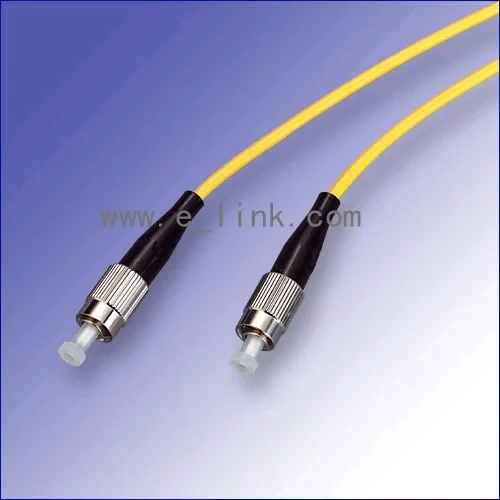
Fiber Optic Patchcord
Factory-terminated jumpers that turn a planned link budget into a working one
11 products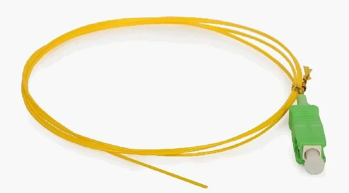
Various Pigtail
Pre-terminated tails that put the factory end face inside your splice tray
12 products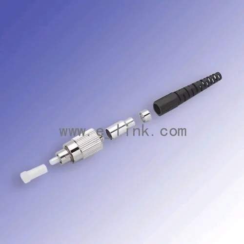
Fiber Optic Connector
Connector bodies and kits for assembly houses and field termination
8 products
Fiber Adapter
Same-type mating sleeves that hold two ferrules on one axis
18 productsGet Pricing On Fiber Optic Splitter
Email the model and quantity and we will reply with pricing, lead time and a datasheet for any item in the fiber optic splitter range.