
PLC and FBT Optical Splitters Compared
Two ways to divide light, why PON standardized on one of them, and how to check whether your budget can carry the split you want.
In This Guide
Two Different Physical Approaches
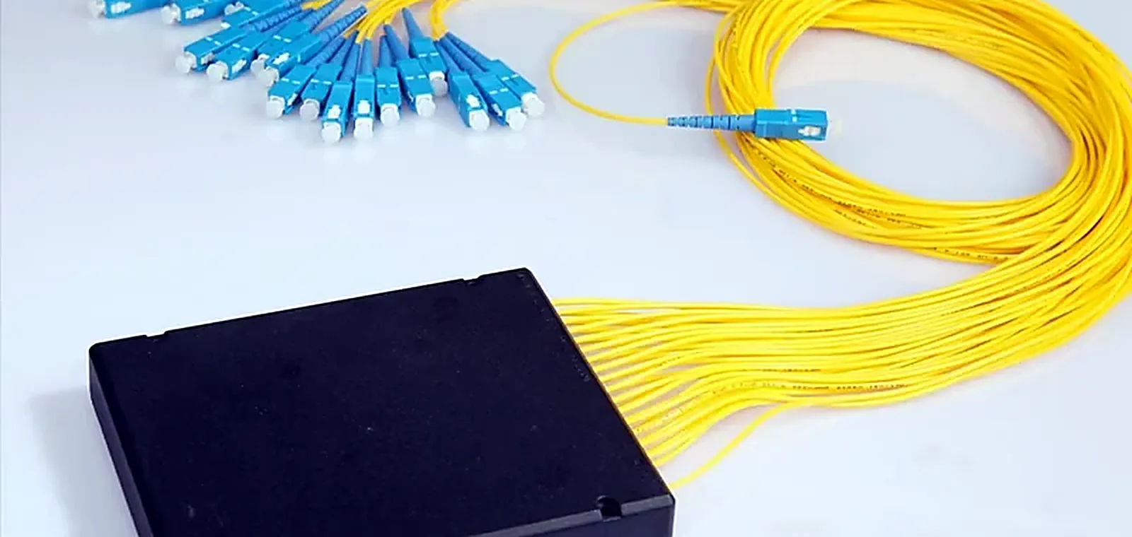
An FBT splitter is made by fusing and drawing fibres together so power couples between them. A PLC splitter is a planar waveguide circuit on a chip, with the splitting geometry defined lithographically. The manufacturing difference produces almost all the behavioural differences that follow.
Uniformity Across Output Ports
A PLC device splits evenly across its ports by design, because the geometry is fixed in the chip. FBT uniformity depends on the fusion process and degrades as the port count rises. On a PON where every subscriber needs an adequate budget, the worst port is the one that matters, and that is where PLC wins.
Browse our Fiber Optic Splitter range
Wavelength Behavior
PLC devices behave consistently across a wide band, which matters when a network carries several PON wavelengths and may add more. FBT is more wavelength selective, which can be turned into an advantage in specific coupler applications but is a liability in general distribution.
Browse our Passive Component range
Where FBT Still Makes Sense
Low split counts, uneven splits where you deliberately want a tap rather than an even division, and wavelength-selective coupling. These are real applications, and the catalog includes WDM couplers for exactly that kind of work. They are simply not what a subscriber distribution network is built from.
Working The Optical Budget
Split ratio is an architecture decision, not a purchasing one. Add the splitter loss, every connector and splice in the path, and the fiber attenuation over the longest branch. Compare the total against transmitter output and receiver sensitivity, and keep margin for the loss a network accumulates as it is maintained.
Browse our Fiber Optic Attenuator range
Packaging Is Part Of The Specification
The same splitter element can be supplied bare, in an ABS box, in a tray, in an LGX cassette or rack mounted, with pigtail length and connector chosen per order. Ordering the right element in the wrong package means re-coiling pigtails in a cabinet, which is where fiber gets damaged.
Testing Before It Leaves
Insertion loss is measured on every output port rather than sampled, and uniformity is checked across the whole device. On a component whose worst port defines the architecture, sampling is not adequate.
Questions This Guide Gets Asked
Which splitter type should I use for PON?
PLC for subscriber distribution. Its uniformity across ports and its consistent wavelength behavior are exactly what a PON needs, and both get harder for FBT as the split count rises.
How do I choose a split ratio?
Work the optical budget over the longest branch: splitter loss plus connector and splice loss plus fiber attenuation, compared against transmitter output and receiver sensitivity, with margin left for future maintenance losses.
Are splitter outputs tested individually?
Yes, insertion loss is measured on every port and uniformity is verified across the device.
What packaging formats can you supply?
Bare fiber, ABS box, tray, LGX cassette and rack mount, with pigtail length, furcation and connector type specified per order so the device fits the enclosure you actually have.
Ranges Covered In This Guide
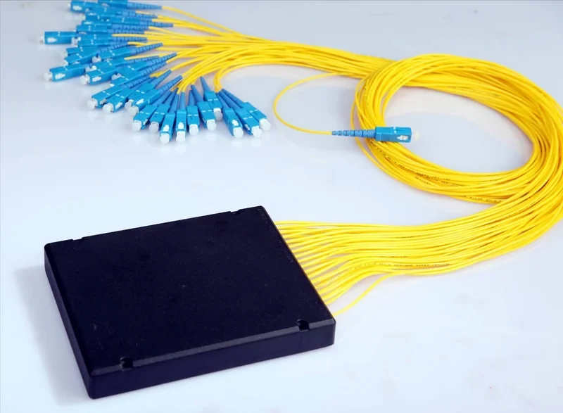
Fiber Optic Splitter
Passive power division, the component PON architecture is built on
6 products
Passive Component
Circulators, isolators and collimators for optical system builders
3 products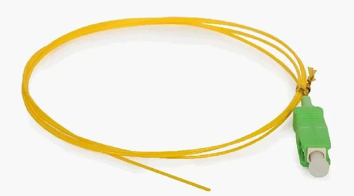
Various Pigtail
Pre-terminated tails that put the factory end face inside your splice tray
12 products
Fiber Optic Attenuator
Controlled loss, for when a receiver is being overdriven
10 productsIndustries and Solutions
Have A Specification To Check
Send the part, the drawing or the link budget. We will confirm what fits before you commit to an order.