
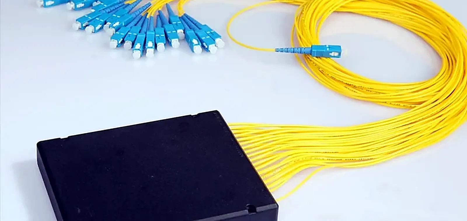
PON Street Cabinet Split Point
How a feeder fiber becomes subscriber ports inside a street cabinet, and which decisions are expensive to reverse
Background
A residential FTTH distribution area served from a single feeder fiber, with subscribers connected progressively as the street is sold. This profile describes how the split point is built from the components in this catalog; it is an engineering profile rather than a record of a specific customer project.
The Challenge
One feeder has to serve an entire distribution area, and the split ratio chosen at build time fixes the optical budget for the life of the plant. Choose too conservatively and the feeder count becomes uneconomic. Choose too aggressively and the last subscriber on the longest branch sits below receiver sensitivity.
Pain Points
- Split ratio decided before the optical budget over the longest branch was worked through
- Splitter packaging that does not fit the cabinet actually installed
- Back reflection from many UPC ports degrading upstream performance
- Ports commissioned progressively over years by crews who were not there at build
- Unused ports left open and contaminated before they are ever used
How It Is Built
The split point is built around a PLC splitter in the packaging format the cabinet takes, with APC terminated outputs, pigtails cut to the tray length and every port capped until it is commissioned. Splice protection, trays and routing come from the same range so sleeve lengths and tray holders match.
Manufacturing and Preparation
- Splitter element screened and packaged in the ordered format
- Output pigtails spliced, furcated and cut to the cabinet tray length
- Insertion loss measured on every output port and uniformity checked across the device
- Ports labeled against the test record and capped
- Trays, splice sleeves and routing hardware kitted with the splitter
Supply Chain Coordination
Splitter, closure or cabinet hardware, pigtails, splice protection and cleaning consumables are quoted and shipped on one order, so the sleeve length matches the tray holder and the pigtail length matches the tray.
Quality Control
Every output port is measured rather than sampled, uniformity is verified across the whole device, and return loss is measured on terminated versions. Port labeling is checked against the test record before packing.
Result
The cabinet is commissioned with a documented loss figure for each port, and subsequent subscriber connections are a patching operation rather than an engineering one.
Customer Benefit
The expensive decisions are taken once, at build time, with the budget worked through. Later connections cost a patch, not a redesign.
Ranges Involved In This Profile
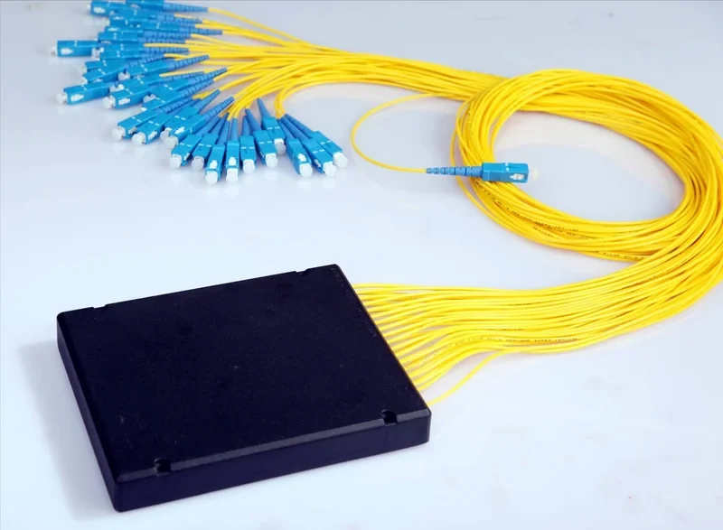
Fiber Optic Splitter
Passive power division, the component PON architecture is built on
6 products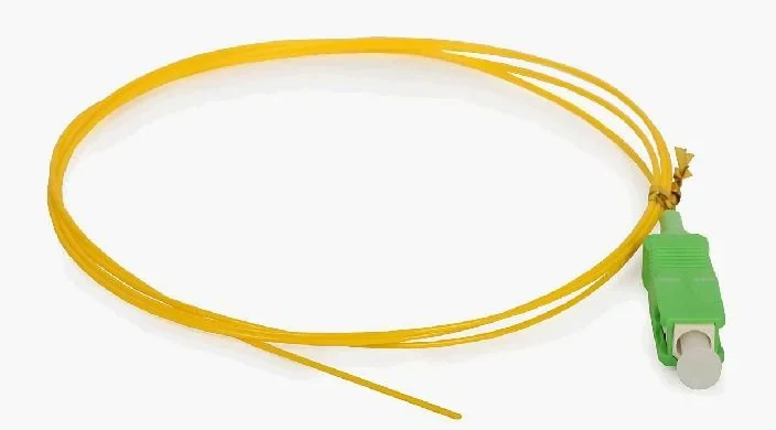
Various Pigtail
Pre-terminated tails that put the factory end face inside your splice tray
12 products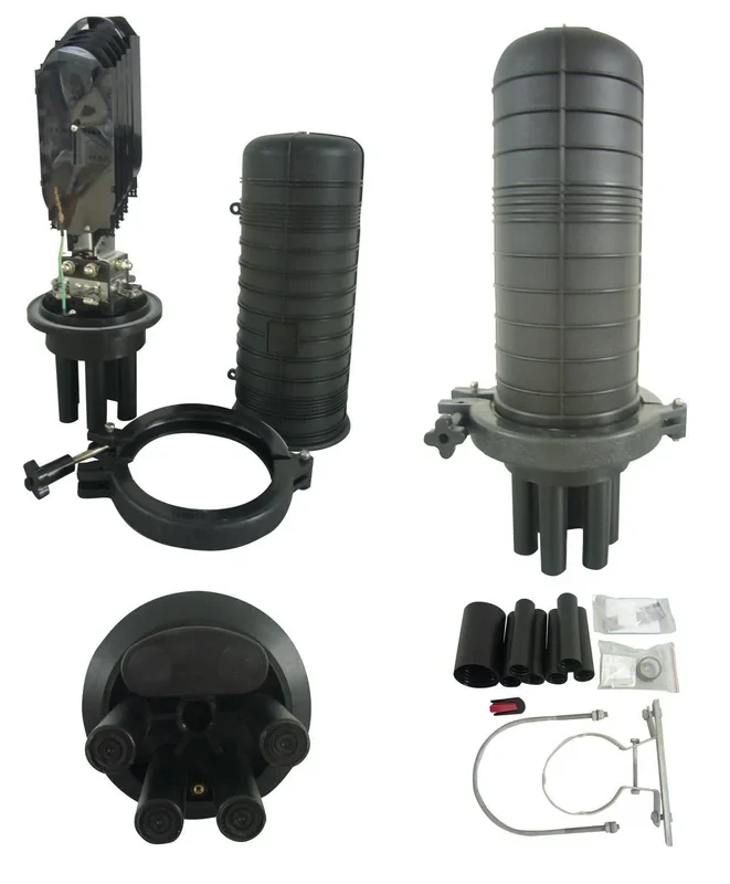
Dome FOSC
Vertical dome closures for pole, wall and hand-hole splice points
9 products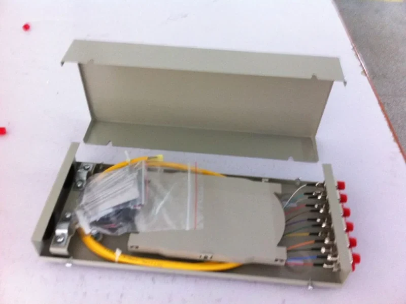
Terminal Box
Wall and pole distribution boxes between the feeder and the drops
7 products
Fiber Cleaning Tool
The cheapest fix for the most common cause of optical loss
3 productsIndustry
Drop-side and distribution hardware for networks whose cost is decided per subscriber
FTTH and Broadband OperatorsBuilding Something Like This
Send us the architecture and the quantities. We will quote the parts and flag the decisions that are expensive to reverse later.