
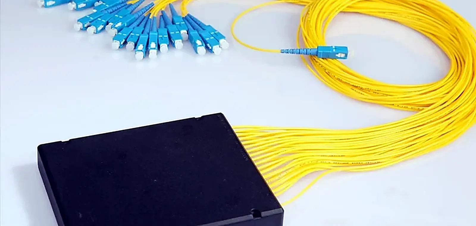
CATV Optical Level Balancing
Bringing an optical distribution tree into level, and keeping reflections out of the picture
Background
An RF-over-glass distribution path feeding node equipment from a headend, where output levels have drifted as branches were added. This profile describes the components and method involved; no customer network or measurement is being reported.
The Challenge
On an RF-over-glass path the failure mode is degradation rather than outage. Levels that are slightly wrong and reflections that are slightly high both show as picture artifacts, and neither will appear as a link failure in a monitoring system.
Pain Points
- Output levels drifting across a distribution tree as branches are added
- Back reflection from UPC end faces on a return-loss-sensitive path
- Attenuation improvised with fiber coils instead of calibrated parts
- Split ratios chosen without a level calculation
- No record of what attenuation was installed where
How It Is Built
Levels are measured first, then brought into range with calibrated fixed attenuators installed on the receive side. The optical path is specified APC throughout so reflections leave the core, and splitter uniformity is verified across all ports rather than sampled.
Manufacturing and Preparation
- Attenuating elements prepared to the target values from the level plan
- Attenuation calibrated per unit against a reference and marked accordingly
- Return loss measured on every unit
- Splitters tested on every output port with uniformity verified
- Measured values supplied with the shipment for commissioning records
Supply Chain Coordination
Attenuators, splitters, APC cords and pigtails are quoted against the level plan on one order, so values and polish types are consistent across the whole tree.
Quality Control
Attenuation value is verified per unit, return loss is measured per unit, wavelength response is checked on samples, and marking accuracy is verified against the measured value.
Result
A distribution tree where each branch lands inside its receiver window, with the installed attenuation values recorded rather than remembered.
Customer Benefit
Picture quality problems stop being investigated as faults and start being prevented as a level plan.
Ranges Involved In This Profile
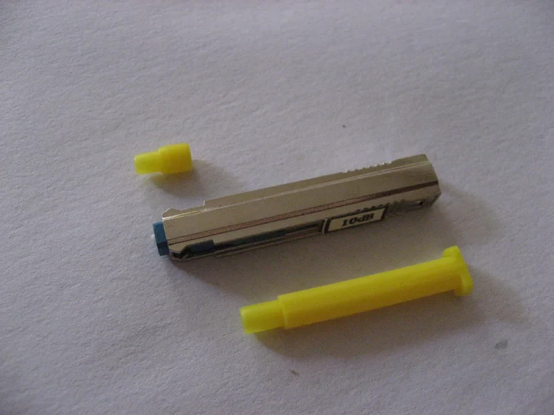
Fiber Optic Attenuator
Controlled loss, for when a receiver is being overdriven
10 products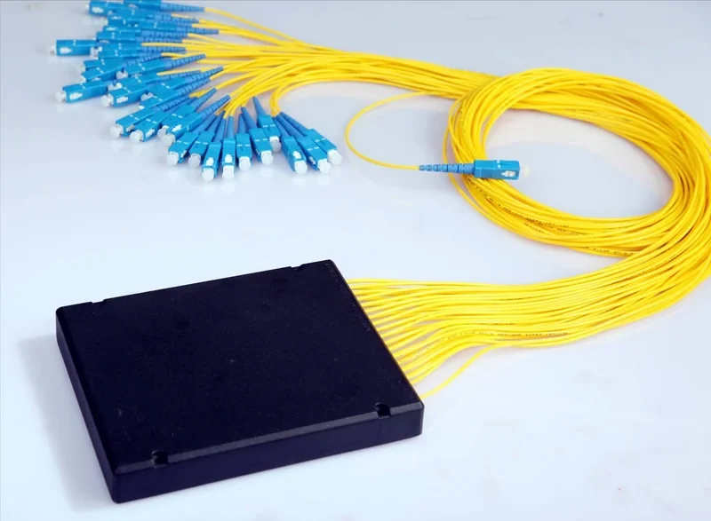
Fiber Optic Splitter
Passive power division, the component PON architecture is built on
6 products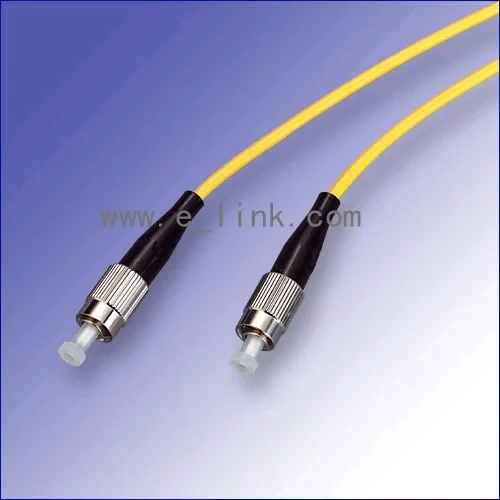
Fiber Optic Patchcord
Factory-terminated jumpers that turn a planned link budget into a working one
11 products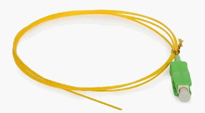
Various Pigtail
Pre-terminated tails that put the factory end face inside your splice tray
12 products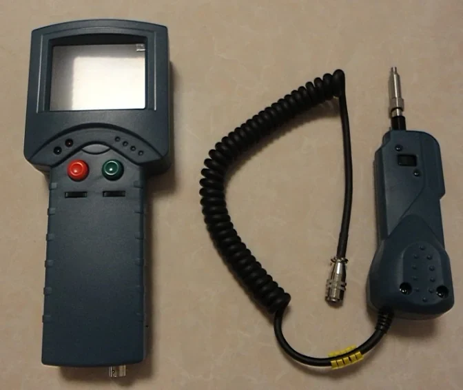
Test Equipment
Splicers, meters, identifiers and inspection tools for people who have to prove the link works
15 productsIndustry
Optical and coaxial distribution where return loss and level balance decide picture quality
CATV and Broadcast NetworksBuilding Something Like This
Send us the architecture and the quantities. We will quote the parts and flag the decisions that are expensive to reverse later.