
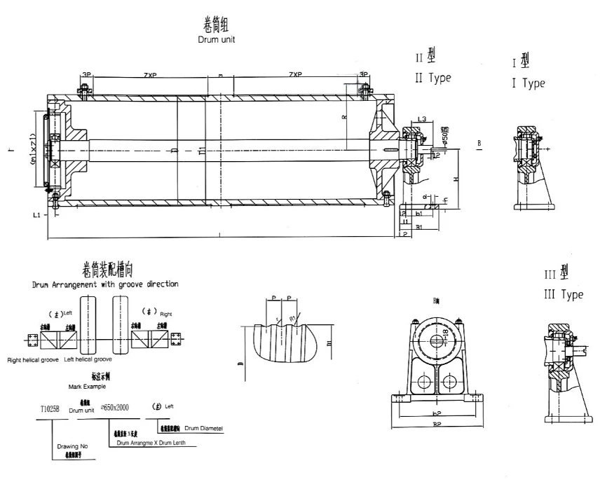
Wire-rope-drum
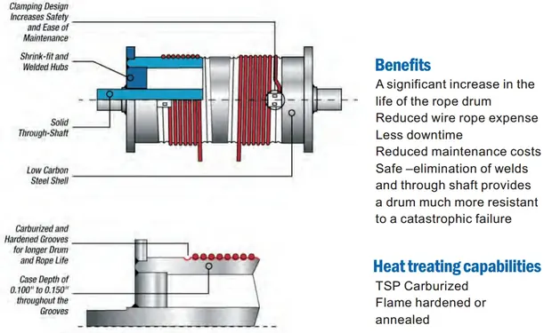
Wire Rope Drum adopt the DIN design conceptions and the Hardness is up to 550 HRC. All the wire rope drum must do MT and UT test to ensure the drum quality. OEM service is available according to the provided drawing.
- Material
- ZG25/ZG35/Q235/Q345
- Hardness
- HRC45-HT55.
- Groove Surface Quench Depth
- ≥2mm
- Max Diameter
- 3000mm
- Heat Treatment
- Must
- Inspection Test
- UT and MT
Quotation in 24 hours · CAD drawing in 48 hours · FEM / DIN / ISO design
Product Overview
<
p
>
Product Gallery
Technical Features
Feature detail for this item is published in the specification table below and in the downloadable catalog.
Where It Is Used
- Spring Driven Wire Rope Drum are mainly used in cranes, stacking equipment or wastewater treatment technology. They are rugged, inexpensive and suitable for mobile equipment without an internal power supply. Motor Driven Wire Rope Drum are used when greater precision and speed control are required
- The wire rope drum is a widely used machine in lifting machinery, used to lift and pull heavy materials in construction sites, port piers, factories, and mines.
- The different classifications of crane drums can help to identify the specific features and applications of each type of drum. The choice of crane drum will depend on factors such as the lifting capacity, speed, and environment, as well as the specific requirements of the lifting operation.
Specifications
Values below are the published standard configuration. Anything outside this range is a customisation question, not a catalogue lookup.
| Material | ZG25/ZG35/Q235/Q345 |
|---|---|
| Hardness | HRC45-HT55. |
| Groove Surface Quench Depth | ≥2mm |
| Max Diameter | 3000mm |
| Heat Treatment | Must |
| Inspection Test | UT and MT |
| OEM | Available |
| NO. Specification Capacity(T) Ratio Screw Pitch Lifting Height(m) Weight(kg) 1 φ300×1000 3.2 2 14 12 264 2 φ300×1500 3.2 2 14 18 342 3 φ400×1000 5 2 16 16 334 4 φ400×1500 10 3 16 16 454 5 φ500×1500 16 3 20 16 753 6 φ500×1500 20 4 20 12 753 7 φ650×2000 32 4 24 16 1500 8 φ800×2000 50 5 28 12 2534 9 φ800×4000 75 5 32 20 3390 10 φ1000×4000 100 6 36 20 6070 | NO. | Specification | Capacity(T) | Ratio | Screw Pitch | Lifting Height(m) | Weight(kg) | 1 | φ300×1000 | 3.2 | 2 | 14 | 12 | 264 | 2 | φ300×1500 | 3.2 | 2 | 14 | 18 | 342 | 3 | φ400×1000 | 5 | 2 | 16 | 16 | 334 | 4 | φ400×1500 | 10 | 3 | 16 | 16 | 454 | 5 | φ500×1500 | 16 | 3 | 20 | 16 | 753 | 6 | φ500×1500 | 20 | 4 | 20 | 12 | 753 | 7 | φ650×2000 | 32 | 4 | 24 | 16 | 1500 | 8 | φ800×2000 | 50 | 5 | 28 | 12 | 2534 | 9 | φ800×4000 | 75 | 5 | 32 | 20 | 3390 | 10 | φ1000×4000 | 100 | 6 | 36 | 20 | 6070 |
|---|---|---|---|---|---|---|---|---|---|---|---|---|---|---|---|---|---|---|---|---|---|---|---|---|---|---|---|---|---|---|---|---|---|---|---|---|---|---|---|---|---|---|---|---|---|---|---|---|---|---|---|---|---|---|---|---|---|---|---|---|---|---|---|---|---|---|---|---|---|---|---|---|---|---|---|---|---|
| NO. | Specification | Capacity(T) | Ratio | Screw Pitch | Lifting Height(m) | Weight(kg) | |||||||||||||||||||||||||||||||||||||||||||||||||||||||||||||||||||||||
| 1 | φ300×1000 | 3.2 | 2 | 14 | 12 | 264 | |||||||||||||||||||||||||||||||||||||||||||||||||||||||||||||||||||||||
| 2 | φ300×1500 | 3.2 | 2 | 14 | 18 | 342 | |||||||||||||||||||||||||||||||||||||||||||||||||||||||||||||||||||||||
| 3 | φ400×1000 | 5 | 2 | 16 | 16 | 334 | |||||||||||||||||||||||||||||||||||||||||||||||||||||||||||||||||||||||
| 4 | φ400×1500 | 10 | 3 | 16 | 16 | 454 | |||||||||||||||||||||||||||||||||||||||||||||||||||||||||||||||||||||||
| 5 | φ500×1500 | 16 | 3 | 20 | 16 | 753 | |||||||||||||||||||||||||||||||||||||||||||||||||||||||||||||||||||||||
| 6 | φ500×1500 | 20 | 4 | 20 | 12 | 753 | |||||||||||||||||||||||||||||||||||||||||||||||||||||||||||||||||||||||
| 7 | φ650×2000 | 32 | 4 | 24 | 16 | 1500 | |||||||||||||||||||||||||||||||||||||||||||||||||||||||||||||||||||||||
| 8 | φ800×2000 | 50 | 5 | 28 | 12 | 2534 | |||||||||||||||||||||||||||||||||||||||||||||||||||||||||||||||||||||||
| 9 | φ800×4000 | 75 | 5 | 32 | 20 | 3390 | |||||||||||||||||||||||||||||||||||||||||||||||||||||||||||||||||||||||
| 10 | φ1000×4000 | 100 | 6 | 36 | 20 | 6070 |
Quality Control
Raw steel arrives with a Material Test Certificate and is spot inspected. Welders hold Class I international qualification. Girders are shot blasted to Sa2.5 before paint, and paint thickness is checked.
Customisation
Capacity, span, lifting height, duty group, power supply, control mode and service environment are all specified per order. Special products customisation is a standard service.
Documentation and Support
Equipment and main parts qualification certificates, electrical drawing diagram, installation operation and maintenance manual, and commissioning instructions ship with the equipment. Online support runs 24/7.
Use Guide
- Confirm the duty group. Count average lifts per hour and average load, not peak tonnage. This sets the FEM classification and drives the whole design.
- Check the building. Wheel load, headroom and hook approach decide whether the unit fits. Ask for the CAD drawing before ordering.
- Specify the environment. Temperature, dust, humidity and any hazardous area classification change the motor, brake and enclosure rating.
- Plan the power supply. Long travel needs a conductor rail or festoon system, which is quoted separately and must match the runway length.
- Book commissioning. Installation supervision or online commissioning support, plus operator training, before the unit goes into production.
Related Products
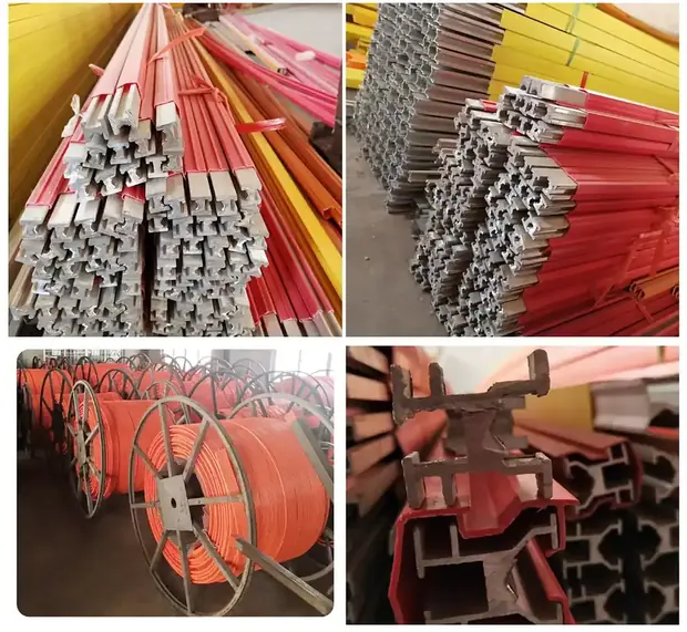
Conductor-rail
- Conductor Material
- Copper(5000A) /Aluminum(3000A).
- Max Allowable Amper
- 5000A/3000A
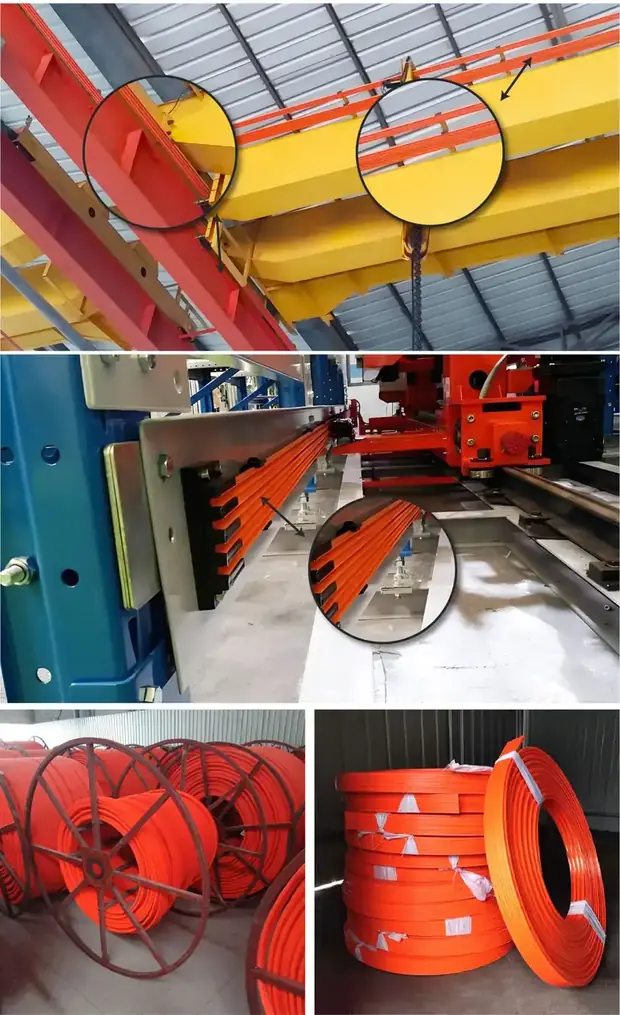
Mobile-conductive-busbar
- Conductor Material
- 99.99% Oxygen Free Copper.
- Max Allowable Amper
- 200A
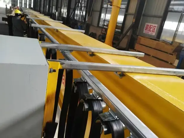
Festoon-system
View specification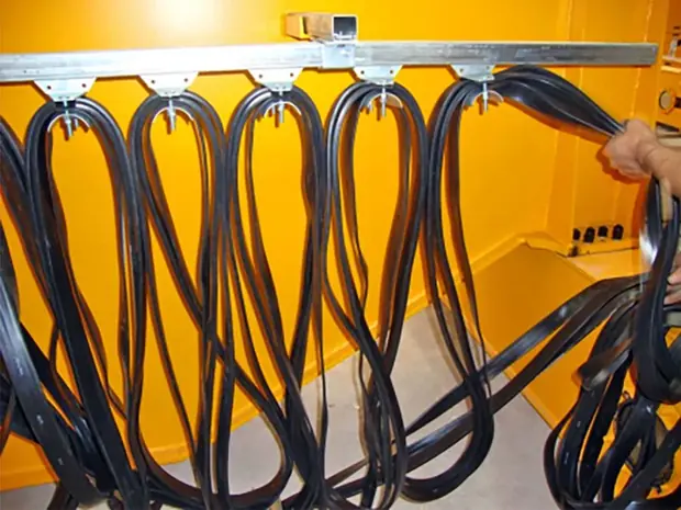
C-track-cable-trolley
View specificationFrequently Asked Questions
What information do you need to quote a wire-rope-drum?
Capacity, span rail centre to rail centre, lifting height, duty or working condition, power supply, travel distance and the service area conditions. A workshop drawing speeds it up considerably.
Is the wire-rope-drum available as a spare part or kit item?
Yes. Sinomac provides a special products customisation service, and free production drawings for regional partners and clients buying crane kits.
How long does a quotation take?
A quotation is issued within 24 hours and a CAD drawing within 48 hours, both free of charge.
What testing is done before shipment?
Every hoist is pre-commissioned before packing and the crane is pre-assembled for a factory acceptance test. A third party inspection can be arranged at your request.
Are your cranes built to FEM and DIN standards?
Yes. Sinomac designs to FEM, DIN and ISO. Duty group is set from your real lifting cycle, so the classification on the nameplate matches how the crane is actually used.
Can you supply a crane kit instead of a complete crane?
Yes. Sinomac supplies hoist, end carriages, drives, control system and anti-sway as a kit, and provides free production drawings of the girder for regional partners and clients buying kits, which lowers shipping cost.
Request a Quotation for the Wire-rope-drum
Send capacity, span, lifting height and duty. A quotation follows within 24 hours.