
Pipe & Tube Parts
Molded connectors manifolds and fittings for fluid circuits that have to seal every time
All 9 Pipe & Tube Parts
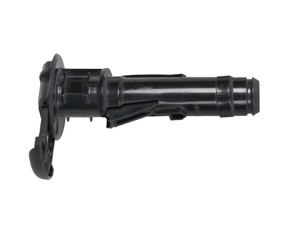
Barbed Pipe Connector with Mounting Bracket
Barbed spigot connector with an integrated flat mounting bracket and clip.
View details →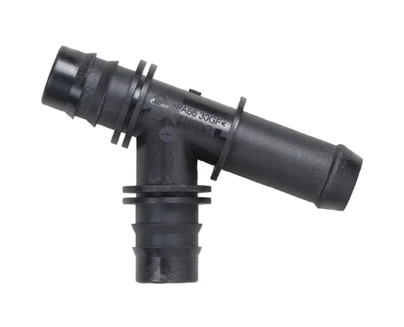
Plastic Tee Pipe Connector
Three-way tee with barbed ends and molded O-ring seats.
View details →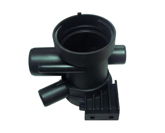
Plastic Pipe Manifold Housing
Multi-port manifold body with a large central bore and several branch spigots.
View details →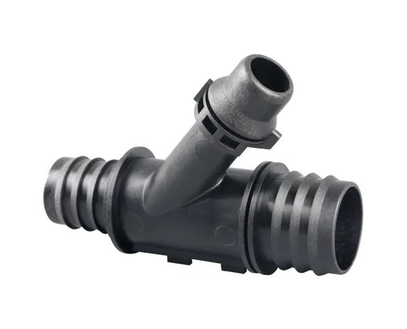
Angled Barbed Pipe Fitting
Angled fitting with deep-barbed run ends and a raised branch spigot.
View details →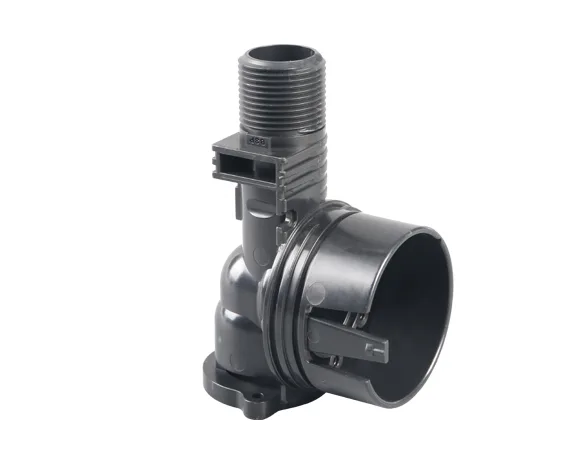
Threaded Pipe Elbow Body
Elbow body with an external thread, a retaining collar and a molded inspection window.
View details →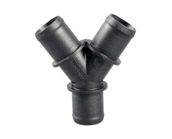
Y Type Pipe Connector
Y connector with three externally threaded ports on a symmetrical split.
View details →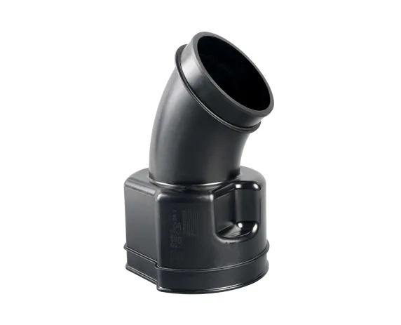
45 Degree Pipe Elbow with Flange
45-degree elbow with a flanged base and a molded-in identification panel.
View details →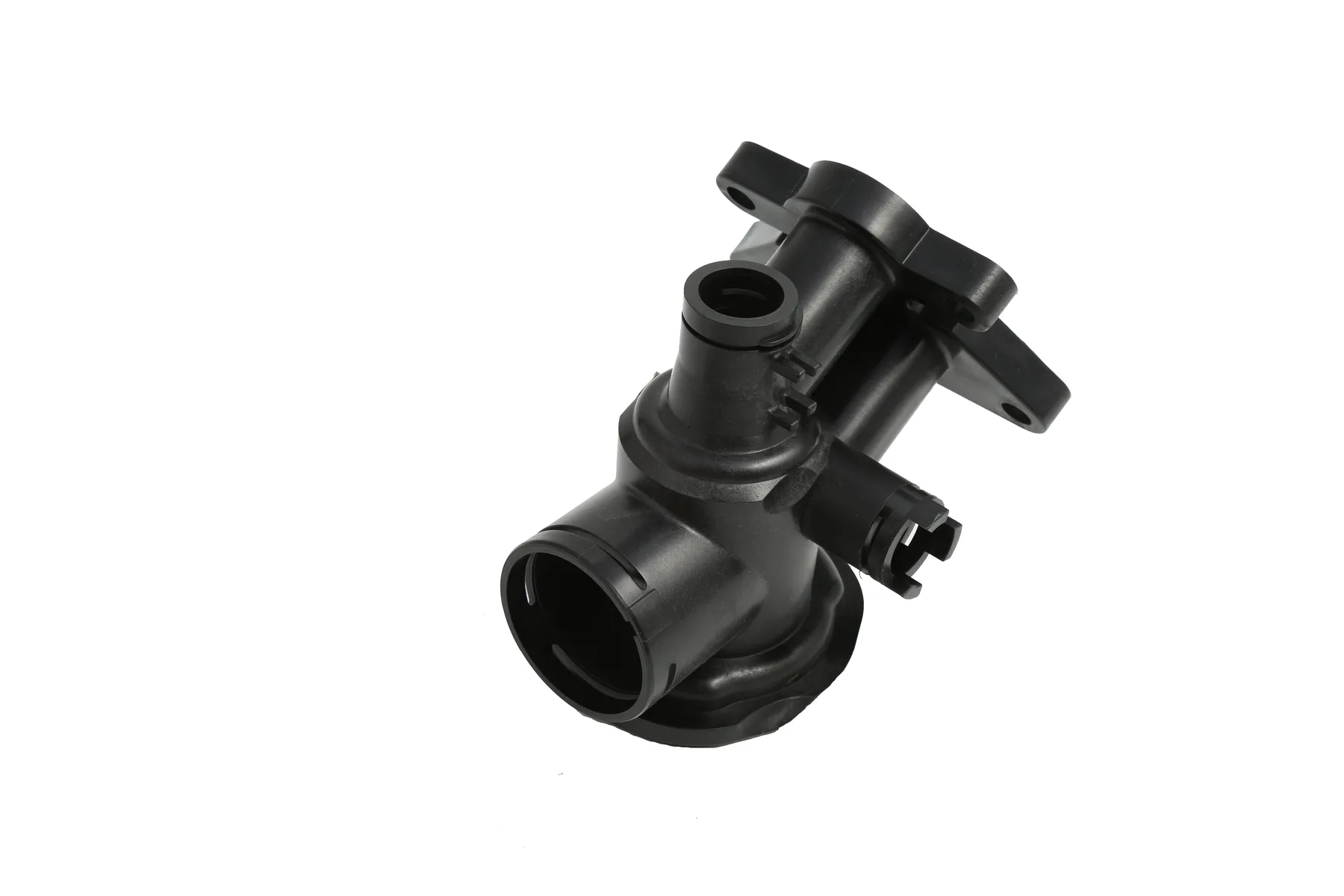
Multi Port Valve Housing
Compact valve housing with several spigots and a molded actuator interface.
View details →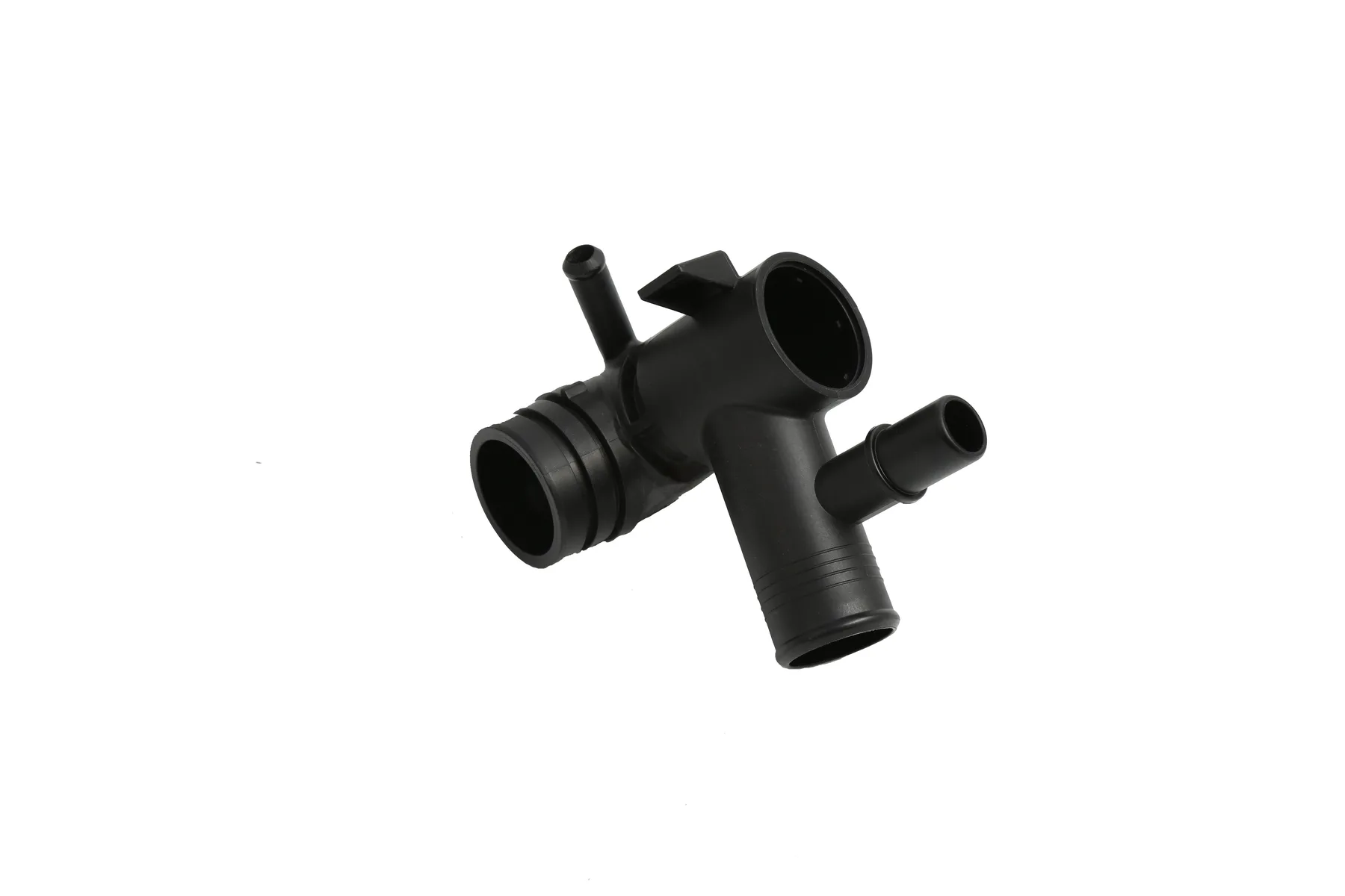
Compact Multi Port Connector
Small multi-port connector with barbed outlets on three axes.
View details →What Goes Wrong Here
A fitting either seals or it leaks, and the failure is always found downstream. Barb profiles that shrink unevenly, a thread that ovalizes on ejection, a manifold whose ports move relative to each other as the part cools — all of them are tooling problems dressed as assembly problems.
Our Answer
Fittings are geometry-heavy parts with side actions on almost every face, so for these tools we run the mold motion simulation before release and step through the open and close sequence with you.
Who This Is For
- Plumbing and sanitary system manufacturers
- Automotive and appliance fluid circuit suppliers
- Irrigation and water treatment equipment makers
- Assemblers sourcing a family of matched fittings
Where These Parts Are Used
- Barbed connectors and tee pieces
- Threaded elbows and adaptor bodies
- Multi-port manifolds and valve housings
- Y connectors and branch fittings
From Enquiry to Delivered Tool
- Step 1
Quotation within two working days from your 3D data, resin and volume
- Step 2
Full 3D mold design completed and reviewed, with the DFM sent for your comment
- Step 3
CNC and EDM machining with inspection after machining and on the electrodes
- Step 4
Mold trial, trial report and sample dimension report, then final and packing inspection
Where Pipe & Tube Parts Are Sourced
Pipe & Tube Parts — Questions We Are Asked
How many pipe & tube parts do you show?
9, all photographed from our own work. Each one has its own page with the tooling route behind it.
What is the lead time on tooling for pipe & tube parts?
Lead time depends on the size of the tool, the number of cavities and the side actions involved, so we put it in the quotation rather than publishing one figure. The quotation itself comes back within two working days. Programme lead times: TBC per project.
Which mold standard will you use?
Yours if you have one. Otherwise DME, Meusburger, HASCO, Progressive or MISUMI — naming it in the enquiry avoids re-specifying components later in the design.
Will we see a design before you cut steel?
Yes. The mold design is completed to one hundred percent detail, checked in a design review meeting, and sent to you together with the DFM for comment before fabrication starts.
What do you need to quote pipe & tube parts?
3D part data, the resin, the expected annual volume and the mold standard. With those four items we can quote without a second round of questions.
Quote a Pipe & Tube Part Tool
Send us the part and the volume. A professional mold quotation with technical comment comes back within two working days.