
Thermoelectric Modules
TEC Multi-Stage Modules
When one stage cannot reach the temperature you need, stages are stacked so each one pumps the heat rejected by the stage above it.
Product Overview
Stacking Stages To Go Colder
A single stage thermoelectric module reaches a maximum temperature differential of roughly 63 to 71 °C at zero heat load, and less than that as soon as it has real work to do. When the application needs a larger differential, the answer is to cascade stages.
In a multi-stage module, a smaller upper stage sits on a larger lower stage. The lower stage has to pump both the useful load and all the electrical power dissipated by the stage above it, which is why each stage grows as you move towards the hot side.
Multi-stage modules are part of our range and are built around the requirement rather than picked from a list. Detailed specifications are issued per project, so send the target cold side temperature, the heat load and the hot side temperature you can hold.
Key Benefits
What Cascading Buys You
Beyond Single Stage Delta-T
Cascading is the standard way past the single stage limit when a compressor or cryocooler is not an option.
Still Solid State
No moving parts, any mounting orientation, silent operation and the same electrical simplicity as a single stage.
Designed Around Your Envelope
Stage count, stage areas and couple counts are chosen for your cold plate, load and supply.
Who It Is For
Engineers Who Ask For Multi-Stage
- Detector and sensor designers who need a cold side well below ambient
- Instrument builders working with dew point or condensation measurement
- Laboratory equipment designers building deep cooled sample stages
- Teams whose single stage design has run out of delta-T at the required heat load
- Applications where a mechanical cooler cannot be used for noise, vibration or orientation reasons
Problems It Solves
What Multi-Stage Solves
- A single stage cannot reach the target cold side temperature at the required heat load
- The hot side runs warm, which eats into the differential a single stage can deliver
- The application needs a deep, stable cold point in a small, silent package
- Mechanical refrigeration is excluded by size, orientation, noise or maintenance
- The cooled element is small but must sit far below ambient
Technical Features
How A Cascade Is Put Together
Stage Ratio
Each stage must pump the load plus the electrical input of every stage above it, so stage area grows towards the hot side.
Electrical Arrangement
Stages can be wired in series for a single supply or driven separately when each stage needs its own operating point.
Diminishing Returns
Each added stage buys less differential than the one before it while consuming more power, so stage count is an engineering decision, not a maximum.
Footprint Planning
The base stage sets the mounting area, and the top stage sets the usable cold plate.
Same Materials
Bi2Te3 based pellets, nickel and stannum plating and the same sealing options as our single stage modules.
Interface Sensitivity
Cascades are far more sensitive to hot side management than single stage modules, so the sink is part of the design from the start.
Specifications
Specifications
Multi-stage modules are configured per application. Send us the duty point and we will issue a specification.
What We Need From You
- Target cold side temperature, and whether it must be reached or held
- Active heat load at that temperature, in watts or milliwatts
- Hot side temperature you can hold, and how the heat is rejected
- Cold plate area available and the total height envelope
- Supply voltage and current available, and whether stages can be driven separately
- Environment: sealed, purged, vacuum, or open to humid air
Detailed catalogue specifications for multi-stage modules are issued per project rather than published, so treat any stage count or delta-T figure as to be confirmed until we have quoted your duty point.
Catalogue Notes
| Data reference | All catalogue values are measured at a hot side temperature Th = 30 °C |
| Flatness | ±0.05 mm |
| Height tolerance | ±0.2 mm |
| Maximum compressive load | 1 MPa |
| Lead wire | 150 mm as default, other lengths and terminations on request |
| Sealing | Silicone gel seal. Specify if you do not want the module sealed |
Symbol Definitions
| Imax | Maximum input current in amperes at Qc = 0 and ΔTmax |
| Vmax | Maximum DC input voltage in volts at Qc = 0 and Imax |
| ΔTmax | Maximum temperature differential in °C at Qc = 0 and Imax |
| QcMax | Maximum heat pumping capacity in watts at Imax and ΔT = 0 |
| Th | Temperature of the hot side during operation |
| Tc | Temperature of the cold side during operation |
Materials And Construction
Construction
| Thermoelectric material | Bi2Te3 based P-type and N-type pellets, purity 99.99 % |
| Substrate | Alumina ceramic, with intermediate plates between stages |
| Plating | Nickel and stannum electroplating |
| Sealing | Silicone gel seal, vacuum anti-humidity process |
| Stage count | Determined by the required differential and heat load |
| Specification | Issued per project, to be confirmed at quotation |
Manufacturing Process
From Ingot To Finished Module
- Bi2Te3 or PbTe crystal growth in our own furnaces
- Wire electrical discharge machining of wafers and pellets for dimensional precision
- Pellet grading, nickel and stannum electroplating
- Patented soldering matched to the working temperature class
- Substrate metallisation and pellet placement
- Vacuum anti-humidity process and silicone gel sealing
- Electrical test of every module, then marking and packing
Quality Control
Every Module Is Tested Before It Leaves The Line
Quality control runs from raw material procurement through crystal growth, pellet selection and module assembly to the dispatch of the finished product. All products are 100 % tested and inspected using test equipment sourced from an American thermoelectric company.
ISO 9001
Quality management system certified
SGS
European Union certification held by the manufacturing company
RoHS
All thermoelectric modules are RoHS compliant
100 % tested
Every module is tested and inspected before dispatch
Customization Options
Every Multi-Stage Module Is A Custom Build
There is no meaningful standard cascade, because the stage ratio follows your heat load.
Stage Geometry
Areas and couple counts sized from your load and target differential.
Drive Arrangement
Series wiring for a single supply, or independent stages for finer control.
Sealing And Environment
Sealed builds for humid air, and dry or purged options for deep cold work.
Comparison With Other Products
Single Stage Against Cascade
| Single stage TEC1 | Multi-stage cascade | |
|---|---|---|
| Maximum differential | ΔTmax 63 to 71 °C at Qc = 0 | Larger, set by stage count and load |
| Power consumption | Lower | Higher, each stage adds input power |
| Height | 3 to 13 mm | Taller, stages stack |
| Hot side sensitivity | Moderate | High, the sink design dominates the result |
| Availability | 158 catalogue codes | Built to requirement |
| Choose when | Target is within single stage reach | Target is beyond single stage reach |
Application Scenarios
Where Cascades Are Used

Use Guide
Before You Ask For A Cascade
- Check whether the single stage really is exhausted. Improving the hot side often recovers more differential than adding a stage.
- Reduce the parasitic load first: better insulation, thinner leads and a radiation shield are cheaper than another stage.
- Be precise about whether the cold temperature must be reached once or held continuously under load.
- Plan the power budget. Each stage adds input power that the sink must also reject.
- Plan for condensation. Deep cold surfaces need sealing, purging or a dry enclosure.
- Send the duty point to us early so the stage ratio can be designed rather than guessed.
Related Products
Other Parts Of The Range
TEC Standard Peltier Modules
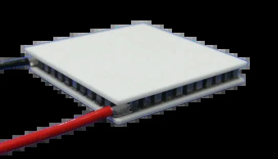
158 catalogue sizes from 10×10 mm to 80×120 mm, Qmax 1.6 to 480 W.
Learn moreTES Micro Thermoelectric Modules
90 codes built on 0.45 to 1.0 mm pellets for optics and sensors.
Learn more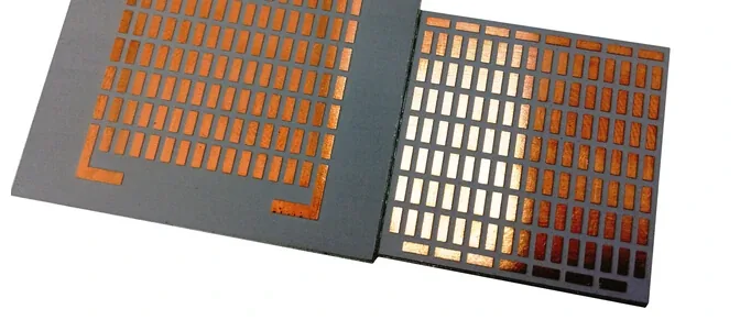
TEC Custom Modules
Your shape, size, lead-out and interface, built from our pellet library.
Learn moreRelated Applications And Guides
Where This Product Is Used
How To Select A Peltier Module
Turn a heat load and a delta-T into a shortlist of part numbers.
Learn more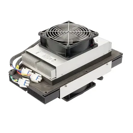
Peltier Module Installation Guide
Mounting force, flatness, thermal interface and sealing.
Learn more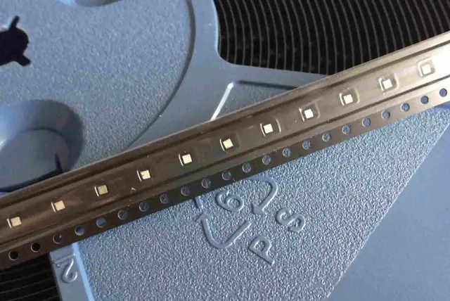
Thermoelectric Module Reliability
Why our modules reach 300,000 hours and what shortens that.
Learn moreFAQ
Frequently Asked Questions About Multi-Stage Modules
How cold can a multi-stage module go?
That depends entirely on the heat load, the hot side temperature and the number of stages. We do not publish a single figure because a number quoted at zero load is misleading. Send the duty point and we will quote a differential we can stand behind.
Can I just stack two standard modules myself?
You can, but the stage ratio will almost certainly be wrong and the interface between them adds thermal resistance exactly where it hurts most. A purpose built cascade performs better in the same height.
Why is there no catalogue table on this page?
Because multi-stage specifications are issued per project. Publishing a generic table would not tell you what your application would actually achieve. Anything you read elsewhere as a headline delta-T is quoted at zero heat load.
What is the biggest mistake in a cascade design?
Under designing the hot side. A cascade rejects the useful load plus all of its own electrical input, so the heat sink has to handle considerably more than the load you started with.
Send Us The Duty Point
Cold side target, heat load, hot side temperature and envelope. That is all we need to tell you whether a single stage will do and what a cascade would look like if it will not.
No forms. Messages reach our engineering desk directly. Reply within 24 hours, Monday to Friday, 9:00 to 17:00 Beijing time.