
Thermoelectric Modules
TEC Miniature Modules
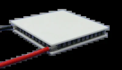
The compact end of the range. When the cold plate is measured in millimetres rather than centimetres, these are the catalogue codes to start from.
Product Overview
A View Of The Catalogue, Filtered By Size
Miniature is a size class rather than a separate product family. The modules come from the same TEC1 and TES1 lines, built on the same Bi2Te3 pellets, with the same plating, sealing and test discipline.
In practice a miniature requirement lands on one of two series. If you need a footprint of 10×10 mm to 20×20 mm and a heat load of a few watts, the TEC1 codes are usually the answer. If the footprint is under 10 mm or the load is a fraction of a watt, the TES1 micro series with sub millimetre pellets is the better starting point.
Use the two catalogue tables to compare. Every value is measured at a hot side temperature of 30 °C, so the codes are directly comparable across the series.
Key Benefits
What The Miniature Codes Give You
Small Enough To Fit
TEC1 codes start at 10×10×4.4 mm and TES1 codes go down to 1.8×3.4×2.4 mm.
Low Drive Current
TES1 codes start at 0.8 A and TEC1 miniature codes at 3.3 A, both drivable from a small controller.
Same ΔT As A Large Module
A small module does not mean a small temperature differential. ΔTmax stays in the 63 to 67 °C band.
Who It Is For
Engineers Who Specify Miniature Modules
- Instrument designers cooling a single sensor, cuvette or reference cell
- Optics teams stabilising a small emitter or detector
- Product designers adding a cooled compartment to a handheld device
- Test engineers building a small temperature controlled stage
- Anyone replacing a discontinued small format Peltier module
Problems It Solves
What Miniature Modules Solve
- A standard 40×40 mm module simply will not fit the mechanical envelope
- The heat load is under a watt and a large module wastes power on its own Joule heating
- The supply can only deliver a fraction of an amp
- Only a small part of the assembly needs to be cooled, not the whole enclosure
- A cooled and heated cycle is needed in a very small space
Technical Features
How The Two Series Compare At Small Sizes
TEC1 From 10 mm
TEC1-00703, TEC1-00704, TEC1-00705 and their siblings are 10×10 mm at 3.5 to 4.4 mm high.
TES1 From 1.8 mm
TES1-00408 is 1.8×3.4 mm on the cold side, the smallest catalogue outline we publish.
Matching The Driver
Vmax from 0.48 V upward means low voltage rails can drive these modules directly.
Round Options
TES1-11930 and TES1-04930 are annular, with the optical path through the centre.
Stepped Faces
Several TES1 codes have a larger hot face so the clamp sits outside the cooled area.
Identical Quality Regime
100 % electrical test, RoHS compliance and silicone gel sealing across both series.
Specifications
Where To Find The Numbers
Miniature codes live inside the two main catalogues. Open the one that matches your footprint.
TEC1 Standard Catalogue
158 codes from 10×10 mm up. Filter the table for 10, 15 or 20 to see the miniature rows.
Open the TEC1 tableTES1 Micro Catalogue
90 codes built on 0.45 to 1.0 mm pellets, footprints from 1.8×3.4 mm including round outlines.
Open the TES1 tableCatalogue Notes
| Data reference | All catalogue values are measured at a hot side temperature Th = 30 °C |
| Flatness | ±0.05 mm |
| Height tolerance | ±0.2 mm |
| Maximum compressive load | 1 MPa |
| Lead wire | 150 mm as default, other lengths and terminations on request |
| Sealing | Silicone gel seal. Specify if you do not want the module sealed |
Symbol Definitions
| Imax | Maximum input current in amperes at Qc = 0 and ΔTmax |
| Vmax | Maximum DC input voltage in volts at Qc = 0 and Imax |
| ΔTmax | Maximum temperature differential in °C at Qc = 0 and Imax |
| QcMax | Maximum heat pumping capacity in watts at Imax and ΔT = 0 |
| Th | Temperature of the hot side during operation |
| Tc | Temperature of the cold side during operation |
Materials And Construction
Construction
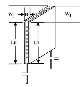
| Thermoelectric material | Bi2Te3 based P-type and N-type pellets, purity 99.99 % |
| Substrate | Alumina ceramic. An aluminium substrate build starts at 40×40 mm |
| Smallest catalogue outline | 1.8 × 3.4 mm cold face, TES1-00408 |
| Smallest TEC1 outline | 10 × 10 mm, 3.4 to 4.4 mm high |
| Sealing | Silicone gel seal unless you specify otherwise |
| Lead wire | 150 mm as default |
Manufacturing Process
From Ingot To Finished Module
- Bi2Te3 or PbTe crystal growth in our own furnaces
- Wire electrical discharge machining of wafers and pellets for dimensional precision
- Pellet grading, nickel and stannum electroplating
- Patented soldering matched to the working temperature class
- Substrate metallisation and pellet placement
- Vacuum anti-humidity process and silicone gel sealing
- Electrical test of every module, then marking and packing
Quality Control
Every Module Is Tested Before It Leaves The Line
Quality control runs from raw material procurement through crystal growth, pellet selection and module assembly to the dispatch of the finished product. All products are 100 % tested and inspected using test equipment sourced from an American thermoelectric company.
ISO 9001
Quality management system certified
SGS
European Union certification held by the manufacturing company
RoHS
All thermoelectric modules are RoHS compliant
100 % tested
Every module is tested and inspected before dispatch
Customization Options
Custom Miniature Builds
Below the smallest catalogue outline, or with an unusual aspect ratio, we build to drawing.
Outline To Drawing
Rectangular, stepped or annular outlines cut to your submount.
Rail Matching
Couple count set so the module runs from the rail you already have.
Lead-Out
Fine gauge leads or pad terminations, exiting on the side your housing allows.
Comparison With Other Products
Choosing Between The Two Series
| Requirement | Choose TEC1 | Choose TES1 |
|---|---|---|
| Footprint 10 to 20 mm | Yes | Possible |
| Footprint under 10 mm | No | Yes |
| Heat load above 2 W | Yes | Only the larger codes |
| Heat load under 1 W | Oversized | Yes |
| Drive current under 1 A | No | Yes |
| Round or annular outline | No | Yes |
Application Scenarios
Typical Miniature Applications


Use Guide
Getting A Small Module To Work
- Add up every path into the cold volume. On a small module, radiation and lead conduction are a large share of the total load.
- Give the hot side a real path to ambient. A small hot face cannot reject heat into a small heat sink.
- Keep the interface layer thin. On a 2.4 mm module a thick grease line is a significant thermal resistance.
- Use a controller with current limit, and add a thermistor if the set point has to be held rather than simply reached.
- Clamp gently and evenly. The 1 MPa limit is easy to exceed on a few square millimetres.
- If the footprint is between series, ask us. We will compare a small TEC1 and a large TES1 for your duty point.
Related Products
Other Parts Of The Range
TES Micro Thermoelectric Modules
90 codes built on 0.45 to 1.0 mm pellets for optics and sensors.
Learn more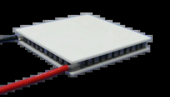
TEC Standard Peltier Modules
158 catalogue sizes from 10×10 mm to 80×120 mm, Qmax 1.6 to 480 W.
Learn more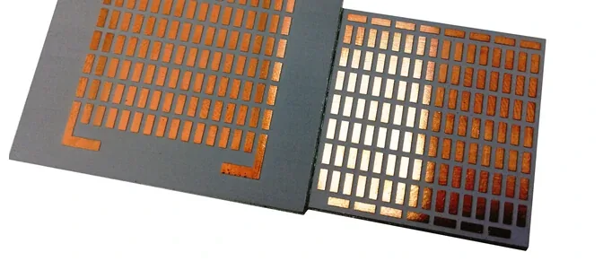
TEC Custom Modules
Your shape, size, lead-out and interface, built from our pellet library.
Learn moreRelated Applications And Guides
Where This Product Is Used
How To Select A Peltier Module
Turn a heat load and a delta-T into a shortlist of part numbers.
Learn more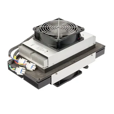
Peltier Module Installation Guide
Mounting force, flatness, thermal interface and sealing.
Learn more
Thermoelectric Module Reliability
Why our modules reach 300,000 hours and what shortens that.
Learn moreFAQ
Frequently Asked Questions About Miniature Modules
Is a miniature module a different product?
No. It is the small end of the TEC1 and TES1 catalogues, built on the same materials and the same process. The distinction is purely one of size and drive current.
What is the smallest module you list?
TES1-00408, with a 1.8×3.4 mm cold face, a 1.8×5.1 mm hot face and 2.4 mm height, rated 0.8 A, 0.48 V and 0.22 W Qmax.
Can I get an aluminium substrate at these sizes?
The aluminium substrate catalogue starts at 40×40 mm. For a smaller aluminium build, send the drawing and we will tell you whether it is feasible.
Do small modules have shorter lives?
The same construction and the same 300,000 hour design life apply. What shortens life at small sizes is usually excess clamping pressure or an inadequate hot side path, not the module itself.
Not Sure Which Small Code To Use
Send the footprint you have and the heat you need to move. We will compare the TEC1 and TES1 candidates side by side and tell you which one is the safer choice.
No forms. Messages reach our engineering desk directly. Reply within 24 hours, Monday to Friday, 9:00 to 17:00 Beijing time.