
Accessories
TE Accessories
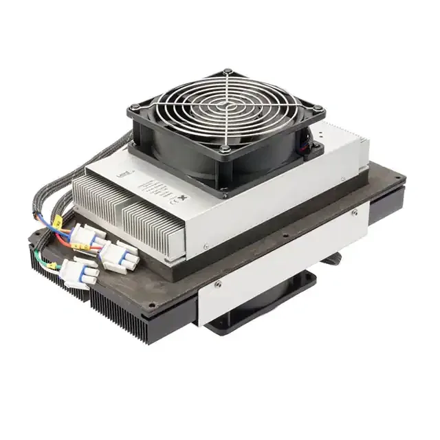
A module on its own is not a cooling system. These are the four supporting items every thermoelectric design needs, supplied alongside the modules.
Product Overview
Four Items That Decide Whether The Module Performs
Most disappointing thermoelectric results are not caused by the module. They are caused by a supply that cannot hold current, a control scheme that switches on and off instead of modulating, no temperature feedback at all, or a thermal interface that adds more resistance than the module can overcome.
We list these four accessories alongside the modules because they are part of the same design decision. Specify them at the same time as the module and the result is predictable.
Tell us the module code you are using and the control behaviour you need, and we will confirm what suits it.
Key Benefits
The Four Accessories
DC Power Supply
Sized on the module Vmax and Imax, with enough headroom that the current does not sag when the module warms up and its resistance changes.
Temperature Controller
Proportional control holds a set point and reduces thermal cycling stress. On and off control reaches a temperature but does not hold it well.
Thermistor
Without feedback there is no control loop. Placement matters as much as the sensor: measure the thing you care about, not the heat sink.
Who It Is For
Who Needs These
- Anyone specifying a thermoelectric module for the first time
- Designers whose module reaches a temperature but cannot hold it
- Teams whose modules are failing early from thermal cycling
- Engineers debugging a cooling result that is far below the datasheet
- Production teams standardising the interface material across a product family
Problems It Solves
What They Solve
- Cooling performance well below the catalogue figure because of interface resistance
- Temperature that overshoots and undershoots because control is on and off
- A supply that cannot deliver rated current continuously at temperature
- Modules failing early from repeated hard switching
- Inconsistent results between units because grease application is not controlled
Technical Features
What To Look For
Supply Headroom
Choose a supply that can deliver the module Imax continuously with margin, not one rated exactly at it.
Proportional Control
Linear or PWM control at a frequency the module tolerates, rather than a relay switching the full current.
Sensor Placement
Put the thermistor on the load or the cold plate, not on the heat sink, or the loop will control the wrong temperature.
Thermal Grease
A thin, even layer on a clean, flat surface. Excess grease is a thermal resistance, not insurance.
Graphite Sheet
A cleaner alternative to grease for production assembly, with repeatable thickness and no pump out.
Clamping
Interface material only works under even pressure. Stay within the 1 MPa maximum compressive load.
Specifications
Availability
Accessories are supplied to suit the module you order rather than as a fixed catalogue.
Power Supply
Specified from the module Vmax and Imax and your control method. Tell us the module code and the mains supply available.
Temperature Controller
Selected for the control accuracy you need and whether the module must heat as well as cool.
Thermistor
Chosen with the controller so the pair works as a loop. Tell us where the sensor can physically be mounted.
Thermal Grease And Graphite Sheet
Grease for prototype and service work, graphite sheet where production repeatability matters more.
Accessory specifications are confirmed at quotation against the module code and control scheme you are using.
Catalogue Notes
| Data reference | All catalogue values are measured at a hot side temperature Th = 30 °C |
| Flatness | ±0.05 mm |
| Height tolerance | ±0.2 mm |
| Maximum compressive load | 1 MPa |
| Lead wire | 150 mm as default, other lengths and terminations on request |
| Sealing | Silicone gel seal. Specify if you do not want the module sealed |
Symbol Definitions
| Imax | Maximum input current in amperes at Qc = 0 and ΔTmax |
| Vmax | Maximum DC input voltage in volts at Qc = 0 and Imax |
| ΔTmax | Maximum temperature differential in °C at Qc = 0 and Imax |
| QcMax | Maximum heat pumping capacity in watts at Imax and ΔT = 0 |
| Th | Temperature of the hot side during operation |
| Tc | Temperature of the cold side during operation |
Materials And Construction
Interface Materials Compared
| Thermal grease | Lowest cost, lowest resistance when applied thinly and evenly |
| Graphite sheet | Repeatable thickness, clean handling, no pump out over thermal cycles |
| Application | Both faces of the module, on clean and flat surfaces |
| Clamping | Even pressure across the module, within the 1 MPa maximum compressive load |
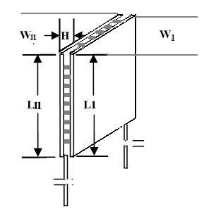
| Flatness | Modules are supplied flat to ±0.05 mm. Mating surfaces should match |
| Sealing | Silicone gel sealed modules still need condensate management on the cold side |
Manufacturing Process
From Ingot To Finished Module
- Confirm the module code and its Vmax and Imax
- Choose the supply with continuous current headroom
- Choose proportional rather than on and off control where the set point must be held
- Place the thermistor on the controlled surface, not the heat sink
- Select grease for prototyping or graphite sheet for production
- Verify clamping force and flatness before final assembly
Quality Control
Every Module Is Tested Before It Leaves The Line
Quality control runs from raw material procurement through crystal growth, pellet selection and module assembly to the dispatch of the finished product. All products are 100 % tested and inspected using test equipment sourced from an American thermoelectric company.
ISO 9001
Quality management system certified
SGS
European Union certification held by the manufacturing company
RoHS
All thermoelectric modules are RoHS compliant
100 % tested
Every module is tested and inspected before dispatch
Customization Options
Specified With Your Module
Send the module code and we will confirm the accessories that suit it.
Supply Matching
Voltage and continuous current chosen from the module rating and duty cycle.
Control Scheme
Cooling only, or cooling and heating with polarity reversal.
Interface Choice
Grease or graphite sheet depending on assembly volume and service plan.
Comparison With Other Products
Grease Against Graphite Sheet
| Thermal grease | Graphite sheet | |
|---|---|---|
| Thermal resistance | Very low when applied thinly | Low and highly repeatable |
| Repeatability | Depends on the operator | Set by the sheet thickness |
| Handling | Messy, needs cleaning | Clean, easy to place |
| Rework | Requires cleaning both faces | Sheet is replaced |
| Long term | Can pump out under cycling | Stable under cycling |
| Best for | Prototypes and service work | Volume production |
Application Scenarios
Where Accessories Matter Most

Use Guide
A Simple Commissioning Sequence
- Assemble with a thin, even interface layer on both module faces and clamp evenly.
- Power the module at a low current first and confirm the cold side falls and the hot side rises.
- Check the hot side temperature under full load. If it climbs, the sink is undersized and no controller will fix it.
- Fit the thermistor on the surface you actually want to control and close the loop.
- Tune for a stable set point rather than the fastest pull down, which reduces cycling stress.
- Record the current draw at steady state and confirm the supply is not at its limit.
Related Products
Other Parts Of The Range
TEC Standard Peltier Modules
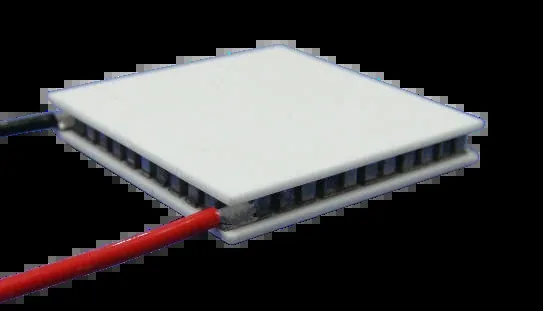
158 catalogue sizes from 10×10 mm to 80×120 mm, Qmax 1.6 to 480 W.
Learn moreThermal Management Assemblies
Air to air, air to liquid, liquid to liquid and plate to plate.
Learn more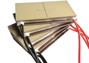
TEA Aluminium Substrate Modules
A 122 W/m·K substrate that raises efficiency 30 to 50 %.
Learn moreRelated Applications And Guides
Where This Product Is Used
How To Select A Peltier Module
Turn a heat load and a delta-T into a shortlist of part numbers.
Learn more
Peltier Module Installation Guide
Mounting force, flatness, thermal interface and sealing.
Learn more
Thermoelectric Module Reliability
Why our modules reach 300,000 hours and what shortens that.
Learn moreFAQ
Frequently Asked Questions About TE Accessories
Do I really need a controller?
If you only need to reach a temperature, a fixed supply can work. If you need to hold a temperature, you need feedback and proportional control. Most disappointing installations are missing the loop, not the cooling capacity.
Grease or graphite sheet?
Grease for prototypes and service work, graphite sheet for volume production where repeatability between units matters more than the last fraction of a degree.
Where should the thermistor go?
On the surface whose temperature you care about. A sensor on the heat sink tells you about the heat sink, not about your load.
Can the same setup heat as well as cool?
Yes, by reversing the module polarity. Say so when you specify the controller and the supply, because not every controller supports reversal.
Specify The Accessories With The Module
Send the module code, the temperature you need to hold and the supply you have. We will confirm the controller, sensor and interface material that suit it.
No forms. Messages reach our engineering desk directly. Reply within 24 hours, Monday to Friday, 9:00 to 17:00 Beijing time.