
Thermal Management Assemblies
Plate To Plate Assemblies
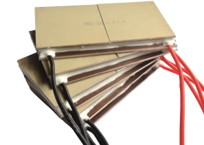
A plate to plate assembly is the simplest configuration: the load bolts to a cold plate, thermoelectric modules sit between that plate and a second plate, and the heat leaves through conduction into whatever the hot plate is attached to.
Product Overview
How This Configuration Works
A plate to plate assembly is the simplest configuration: the load bolts to a cold plate, thermoelectric modules sit between that plate and a second plate, and the heat leaves through conduction into whatever the hot plate is attached to.
There are no fans and no fluid inside the assembly itself, which makes it the quietest and most compact of the four configurations, and the one with the fewest failure modes.
It puts the responsibility for heat rejection on the mounting structure. If the hot plate is bolted to a chassis or a larger heat sink that can take the load, this configuration is very hard to beat.
Key Benefits
Why This Configuration
Fewest Failure Modes
No fans and no pumps inside the assembly means nothing inside it wears out.
Lowest Profile
Two plates and a module array make the thinnest assembly of the four configurations.
Direct Conduction
Removing the air or fluid step removes a thermal resistance and a noise source at the same time.
Who It Is For
Who Uses It
- Designers mounting a detector, laser or sensor directly on a cold surface
- Equipment builders whose chassis can act as the heat sink
- Vibration sensitive instruments that cannot tolerate a fan
- Vacuum and sealed applications where air or fluid is not available
- Compact assemblies where every millimetre of height counts
Problems It Solves
What It Solves
- A fan cannot be used because of noise, vibration, contamination or vacuum
- The available height rules out a finned exchanger
- The load is a solid component that can be bolted straight to a plate
- The chassis is already a good heat sink and should be used as one
- The design needs the fewest possible moving parts
Technical Features
Design Considerations
Flatness Is Everything
Both plate faces must be flat and clean. Conduction assemblies live or die on the interface.
Clamping
Even clamping across the module array, staying inside the 1 MPa maximum compressive load.
Aluminium Substrate Option
A TEA1 module is a natural fit here, because the plate is metal and the module plate is metal.
Hot Plate Path
The assembly only works if the structure behind the hot plate can genuinely take the heat.
Condensation And Sealing
A cold plate below dew point will condense, so seal or purge the volume around it.
Thermal Interface
Grease or graphite sheet on both faces, thin and even, applied to a clean surface.
Specifications
Specification
Assemblies are built around your duty point using modules from our own catalogue.
What We Need To Configure An Assembly
- Heat load to remove, in watts, and the temperature it must be held at
- Ambient temperature range and the worst case you must still work in
- Enclosure or process volume, and how the cold side is coupled to it
- Available supply voltage and current, and whether control is on and off or proportional
- Space envelope, mounting orientation and any ingress protection requirement
- Flow rate and coolant type, for any liquid coupled configuration
Assemblies are configured per project from our module catalogue rather than sold as fixed catalogue items, so capacity and dimensions are confirmed at quotation.
Catalogue Notes
| Data reference | All catalogue values are measured at a hot side temperature Th = 30 °C |
| Flatness | ±0.05 mm |
| Height tolerance | ±0.2 mm |
| Maximum compressive load | 1 MPa |
| Lead wire | 150 mm as default, other lengths and terminations on request |
| Sealing | Silicone gel seal. Specify if you do not want the module sealed |
Symbol Definitions
| Imax | Maximum input current in amperes at Qc = 0 and ΔTmax |
| Vmax | Maximum DC input voltage in volts at Qc = 0 and Imax |
| ΔTmax | Maximum temperature differential in °C at Qc = 0 and Imax |
| QcMax | Maximum heat pumping capacity in watts at Imax and ΔT = 0 |
| Th | Temperature of the hot side during operation |
| Tc | Temperature of the cold side during operation |
Materials And Construction
What Goes Into The Assembly
| Modules | TEC1 ceramic or TEA1 aluminium substrate modules from our own production |
| Interface | Thermal grease or graphite sheet, selected for the clamping method |
| Sealing | Silicone gel sealed modules, with condensate management on the cold side |
| Control | Temperature controller and thermistor, supplied as accessories |
| Test | Modules 100 % tested before assembly, assemblies functionally tested |
| Specification | Issued per project, to be confirmed at quotation |
Manufacturing Process
From Ingot To Finished Module
- Duty point review: heat load, set point, ambient and control method
- Module selection from the TEC1, TEA1 or TES1 catalogue
- Cold side and hot side exchanger sizing around the selected module
- Interface, sealing and condensation management
- Electrical design: supply, controller and sensor arrangement
- Build, test and documentation before shipment
Quality Control
Every Module Is Tested Before It Leaves The Line
Quality control runs from raw material procurement through crystal growth, pellet selection and module assembly to the dispatch of the finished product. All products are 100 % tested and inspected using test equipment sourced from an American thermoelectric company.
ISO 9001
Quality management system certified
SGS
European Union certification held by the manufacturing company
RoHS
All thermoelectric modules are RoHS compliant
100 % tested
Every module is tested and inspected before dispatch
Customization Options
Configured, Not Catalogued
Every assembly is put together from our module range around the load you actually have.
Capacity
Module count and size chosen for your heat load and delta-T.
Supply And Control
Built for the voltage you have, with proportional or on and off control.
Mechanical Integration
Mounting, orientation, sealing and service access designed in.
Comparison With Other Products
Compared With The Other Configurations
| Configuration | Cold side | Hot side | Best when |
|---|---|---|---|
| Air to air | Air | Air | A sealed enclosure has to be cooled below ambient with no plumbing |
| Air to liquid | Air | Liquid | Heat must leave the area entirely, or ambient air is hot or dirty |
| Liquid to liquid | Liquid | Liquid | A circulating fluid loop needs to be conditioned |
| Plate to plate | Conduction | Conduction | The load bolts straight to a cold plate and space is tight |
Use Guide
Making It Work In The Field
- Machine both plate faces flat and check them before assembly. A 0.05 mm gap will dominate your thermal budget.
- Use a thin, even interface layer. More grease is not better.
- Clamp through the module array evenly, using a plate that will not bow, and stay under 1 MPa.
- Verify that the structure behind the hot plate can actually take the rejected heat before you build.
- Seal or purge around the cold plate if it will run below the dew point.
- Consider an aluminium substrate module, which tolerates the clamping loads a metal to metal build applies.
Related Products
Other Parts Of The Range
TEC Standard Peltier Modules
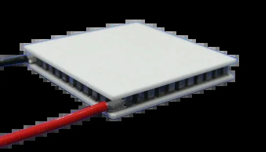
158 catalogue sizes from 10×10 mm to 80×120 mm, Qmax 1.6 to 480 W.
Learn moreTEA Aluminium Substrate Modules
A 122 W/m·K substrate that raises efficiency 30 to 50 %.
Learn more
TE Accessories
Power supplies, controllers, thermistors and thermal interface materials.
Learn moreRelated Applications And Guides
Where This Product Is Used
How To Select A Peltier Module
Turn a heat load and a delta-T into a shortlist of part numbers.
Learn more
Peltier Module Installation Guide
Mounting force, flatness, thermal interface and sealing.
Learn more
Thermoelectric Module Reliability
Why our modules reach 300,000 hours and what shortens that.
Learn moreFAQ
Frequently Asked Questions About Plate To Plate Assemblies
Do I need fans at all?
Not inside the assembly. Something still has to reject the heat, so either the chassis behind the hot plate does it, or the hot plate is attached to a heat sink that has its own airflow.
How flat do the plates need to be?
Our modules are supplied to a flatness of ±0.05 mm. Your plates should be at least as good, because any gap between plate and module is a thermal resistance in the worst possible place.
Can I use aluminium substrate modules here?
They are a good fit. A metallic substrate tolerates clamping and vibration far better than ceramic in a bolted plate to plate build, and the substrate conducts 122 W/(m·K) against 12 for ceramic.
What is the most common mistake?
Assuming the mounting structure can take the heat. A plate to plate assembly does not create a heat sink, it only delivers the heat to one.
Send Us Your Heat Load
Tell us the watts to remove, the temperature to hold and the ambient you have to survive. We will configure the assembly around modules from our own production.
No forms. Messages reach our engineering desk directly. Reply within 24 hours, Monday to Friday, 9:00 to 17:00 Beijing time.