
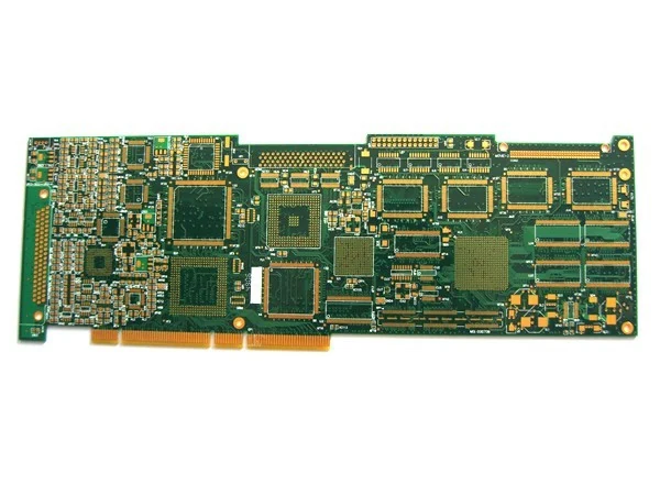
What Each Rigid PCB Tolerance Actually Controls
A capability table is a list of numbers until you know which failure each one prevents. This walks through the rigid PCB tolerances we publish and explains what goes wrong when each is missed.
On This Page
Outline Dimension Tolerance
Held at ±0.10 mm, which is 4 mil. This is the tolerance that decides whether the board drops into the enclosure. It also decides whether a card sits properly in a slot guide and whether a rear port cluster lines up with a chassis aperture. When a board arrives and will not fit, this is almost always the number that was missed.
Hole Position Tolerance
Held at ±0.05 mm, which is 2 mil. On a single sided board this controls whether mounting holes line up with the standoffs. On a multilayer board it controls something more serious: whether a drilled via lands inside its inner layer pad. Miss it on a twelve layer board and the panel is scrap after lamination, with no way to recover it.
Plated Hole Diameter Tolerance
Held at ±0.075 mm on plated holes and ±0.05 mm on non-plated holes. Plated holes have the looser tolerance because plating adds material to the wall. Component leads and press-fit parts care about the finished diameter, so specify the finished size rather than the drill size.
Plated Wall Thickness
Held at 0.025 mm, which is 1 mil. This is the mechanical strength of the barrel. It matters most on boards with connectors and terminal blocks, where a screwdriver load goes into the joint, and on boards that get reworked, where repeated heating stresses the barrel.
Warpage
Held at 0.75% or better across the panel. Warpage decides whether a processor socket sits flat, whether a board can be held down in an assembly fixture and whether it will pass through a reflow oven without distorting further.
Electrical Verification
Three checks confirm what the mechanical tolerances cannot. Open and short testing at 50 to 300 V verifies the netlist. Hole resistance below 300 ohms confirms the barrels are properly plated. Isolation resistance above 10 to the power 12 ohms confirms there is no leakage between nets.
| Tolerance | Value | What it prevents |
|---|---|---|
| Outline dimension | ±0.10 mm | Boards that will not fit the enclosure |
| Hole position | ±0.05 mm | Vias missing inner layer pads |
| Plated hole diameter | ±0.075 mm | Leads that will not enter the hole |
| Non-plated hole diameter | ±0.05 mm | Mounting hardware that does not fit |
| Plated wall thickness | 0.025 mm | Barrel cracking under mechanical or thermal load |
| Minimum solder bridge | 0.10 mm | Mask slivers between fine pitch pads |
| Warpage | ≤0.75% | Sockets that will not seat flat |
Boards This Guide Applies To
Catalogue items where the decisions in this guide have already been made one way or another.
Twelve Layer Immersion Gold Board With Edge Connector Fingers

Eight Layer Board With Electroplated Gold For Contact Surfaces
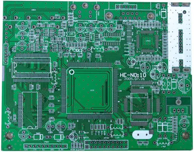
Double Sided FR4 Board With Lead Free HASL
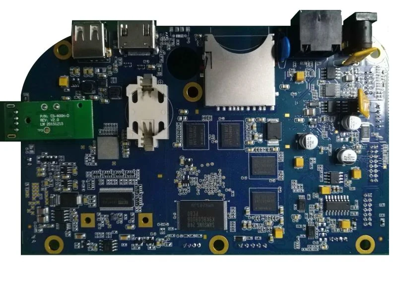
Assembled Multi Port Board With USB Card Slot And Shielded Modules
Other Guides In The Knowledge Center
Eight guides in total, covering layer count, finishes, thermal management, flex design, tolerances and buying.
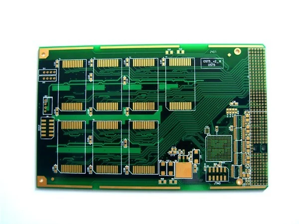
Layer count is the single decision that most affects the price and the electrical behaviour of a board. This guide sets ...
Three surface finishes cover almost every board we build. Choosing between them is not a quality decision, it is a fitne...
When a board runs hot the usual fixes are a bigger heatsink or a bigger enclosure. A metal core board attacks the proble...
Questions About This Topic
Are these tolerances guaranteed on every board?
They are the published capability of the rigid line. Send your drawing and we will confirm against your specific board before quoting.
What if my design needs tighter than this?
Tell us which dimension and what value. It is better to establish that before tooling than after the first article measurement.
Do you supply a dimensional report?
Tell us what measurements you need recorded and we will confirm what we can supply with the shipment.
Have A Board That This Guide Does Not Answer
Send the files and the question. We will tell you what the published capability allows and where your design sits against it.