
Application Example Flex Circuit Replacing A Wiring Harness
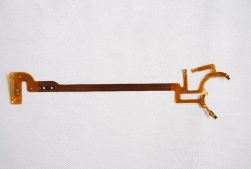
A single layer polyimide flexible circuit with a long main run, two branched arms and a stiffened ZIF tail, built to replace a hand-assembled multi-wire harness inside a mechanism.
What Had To Be Solved
A wiring harness is the least repeatable part in most assemblies. Conductor positions vary between units, splices are a failure point, and the whole part depends on hand labour that cannot be inspected the way an etched circuit can.
Customer name, order volume and project dates are confidential and are not published.
Four Things That Had To Stop Happening
- Conductor routing that differs on every unit built
- Splice joints failing after installation
- Harness bundles too thick to pass through the mechanism
- Flex tails buckling instead of entering the ZIF connector squarely
How The Board Answers Them
The harness is replaced by one etched circuit. Branch arms reach both sub-assemblies as part of the same conductor pattern, so there are no splices. Minimum track and gap of 0.05 mm fit the full conductor count into a narrow ribbon, and a laminated stiffener under the ZIF tail lets it enter the connector square.
How The Board Is Produced
Each stage below runs inside our own plant in Fuyong, Shenzhen.
Stage 1
Copper etched on polyimide base material
Stage 2
Coverlay laminated over the conductors with openings at the contact areas
Stage 3
Stiffener laminated beneath the ZIF tail
Stage 4
Outline punched or laser cut to ±0.05 mm
Stage 5
Contact areas finished to the specified plating
Where Coordination Happens
The bare board and the assembly are handled by the same plant, so the surface finish, the panel format and the reflow route are decided together rather than negotiated between two suppliers. There is no shipping leg between fabrication and assembly, and no handover where damage or delay can enter.
Components are either bought here on a turnkey basis or consigned by you, with the split marked line by line on the bill of materials.
What Is Verified
- Peeling strength of 1.0 kgf/cm on adhesive copper and 0.5 kgf/cm on adhesiveless copper
- Outline tolerance verified at ±0.05 mm after punching or laser cutting
- Coverlay opening registration checked against the contact areas
- Plated hole tolerance held at ±0.05 mm
- Stiffener thickness checked against the connector insertion specification
Where This Board Stands Today
The circuit is a standard catalogue item in the flexible family. Base material, copper thickness and outline tolerance are the published figures for our flex line.
Boards In The Same Family
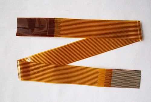
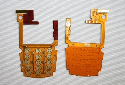
Other catalogue items built on the same line to the same published tolerances.
Questions About This Example
Can you tell me who this board was built for?
No. Customer names, order volumes and project dates are confidential and are not published. What is published is the board, its family and the process tolerances behind it.
Can you build the same board for me?
The board shown is a flex pcb catalogue item. Send your own files and we will quote against the same process and the same published tolerances.
What if my requirement is close but not identical?
That is the normal case. The capability tables define the envelope, and anything inside it can be built. Anything outside it we will tell you about before tooling.
Which industries does this apply to?
This example sits in medical devices, but the same board family is used across the other sectors in the catalogue as well.
Bring Us A Board With The Same Problem
Send the files and describe what has to stop happening. We will tell you which family and which tolerances solve it before quoting.