
How To Choose A PCB Layer Count
Layer count is the single decision that most affects the price and the electrical behaviour of a board. This guide sets out when two layers is enough, when four is the right answer, and what actually forces a design to six, ten or twelve.
On This Page
Start From Routing Density Not From Habit
Most boards are specified at a layer count somebody chose during the last project. The honest starting point is different: lay the board out on two layers and see where it fails. If every net routes and the ground return paths are short, two layers is the correct answer and anything more is money spent for nothing.
Two layers fails in three predictable ways. The routing does not close. The ground return has to wander around obstacles. Or a fine pitch part cannot escape its own footprint. Each of those failures points at a different fix.
What Four Layers Actually Buys You
Going from two layers to four is not about getting more routing space, even though that is how it is usually described. It is about getting a continuous ground plane. Every fast signal on the board then has a return path directly underneath it, which is what keeps loop area small and radiated emissions low.
The second gain is a power plane. On a two layer board the supply rail is a trace, and it drops voltage along its length. On four layers it is copper across the whole board.
- Any board with a BGA or a part below 0.5 mm pitch
- Any board that has to pass radiated emissions testing
- Any board with more than two supply rails
- Any board where the two layer layout could not close the routing
When Six Layers Is The Right Step
Six layers gives four routing layers and two planes. The usual trigger is physical: a board that has to fit a slot, a DIN rail card or a narrow strip, where the constraint is board width rather than net count. Releasing two more routing layers often shrinks the outline enough to avoid redesigning the enclosure, which is almost always cheaper.
Our minimum board thickness for six layer construction is 1.00 mm, which is 40 mil, against 0.40 mm for four layers. If the finished thickness is fixed by a connector, check that first.
Ten Twelve And Above
Above eight layers the driver is usually escape routing. A large BGA consumes a routing channel per row of balls, so two or three large devices on one board will exhaust six routing layers on escape alone. Ten and twelve layer builds give those layers back without resorting to blind and buried vias, which cost considerably more.
| Layers | Typical use | Minimum thickness | Usual finish |
|---|---|---|---|
| 2 | Power supplies, interface cards, instrument boards | See specification | Lead-free HASL |
| 4 | Fine pitch SMD with ground and power planes | 0.40 mm (16 mil) | Immersion gold |
| 6 | Dense boards in a narrow outline | 1.00 mm (40 mil) | Lead-free HASL |
| 8 | Boards with edge fingers or contact surfaces | 1.20 mm (48 mil) | Gold plating |
| 10 to 16 | Multi-BGA boards and backplanes | See specification | Immersion gold |
The Numbers That Constrain The Choice
Whatever layer count you land on, the same process limits apply. Minimum trace width and space are 0.075 mm, which is 3 mil. Minimum finished hole is 0.20 mm, which is 8 mil. Maximum panel dimension is 450 x 660 mm. Warpage is held at 0.75% or better. If your design needs something outside that envelope, that is worth knowing before you choose a layer count, not after.
Boards This Guide Applies To
Catalogue items where the decisions in this guide have already been made one way or another.
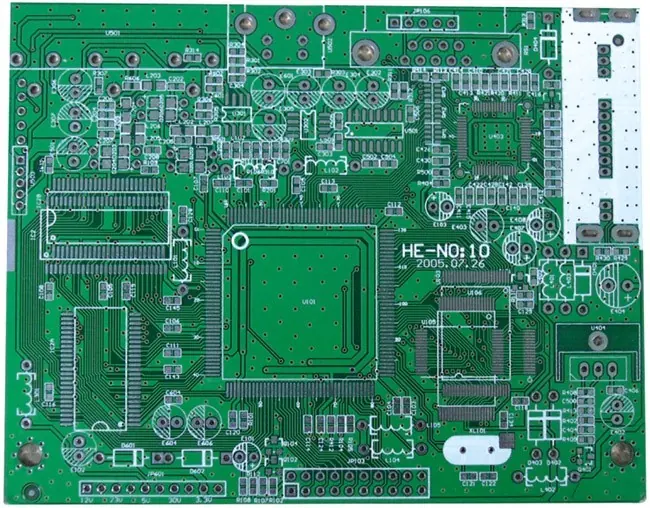
Double Sided FR4 Board With Lead Free HASL
Four Layer Immersion Gold Board For Dense SMD Routing
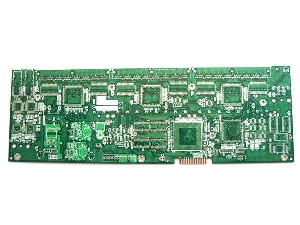
Six Layer Board With Lead Free HASL For Larger Controllers
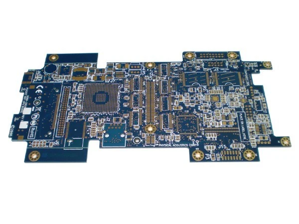
Ten Layer Immersion Gold Board For High Density Digital Designs
Other Guides In The Knowledge Center
Eight guides in total, covering layer count, finishes, thermal management, flex design, tolerances and buying.

Three surface finishes cover almost every board we build. Choosing between them is not a quality decision, it is a fitne...
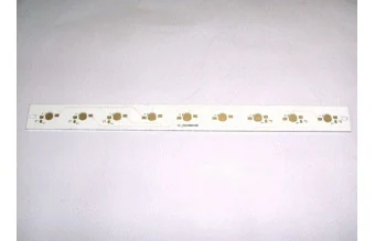
When a board runs hot the usual fixes are a bigger heatsink or a bigger enclosure. A metal core board attacks the proble...
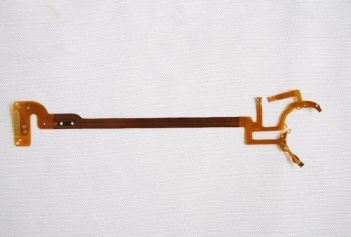
Flexible circuits fail in ways rigid boards do not: creases in the wrong place, copper fatigue at a fold, tails that buc...
Questions About This Topic
Is a four layer board twice the price of a two layer board?
No. The extra cost comes from two more imaging and etching passes plus a lamination cycle, not from doubling the material. Send both versions of the design and we will quote them side by side.
Can I mix layer counts within one product?
Yes, and most products do. A controller board might be four layers while its interface card is two.
What is the maximum layer count you build?
16 layers, as published in our rigid capacity table.
Have A Board That This Guide Does Not Answer
Send the files and the question. We will tell you what the published capability allows and where your design sits against it.