
500X Electro Pneumatic Transducer
The 500X electro pneumatic transducer converts a current or voltage electrical input signal into a linearly proportional...
What This Model Does
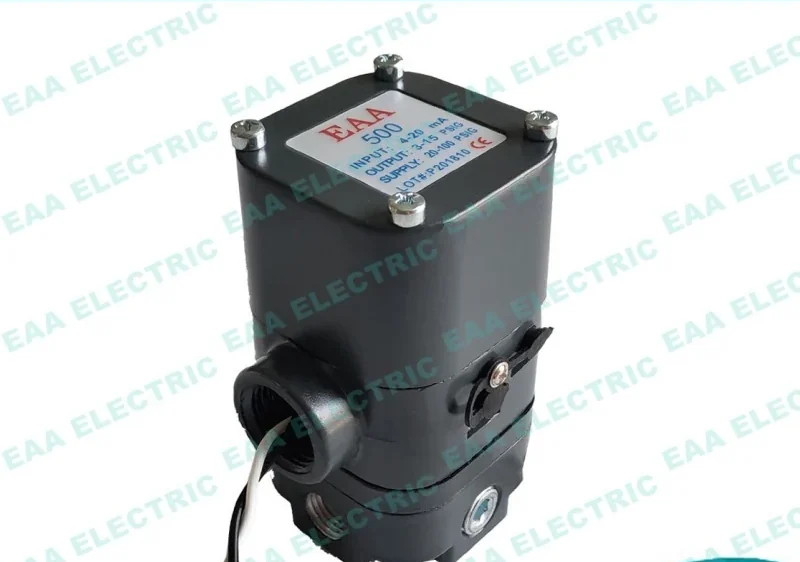
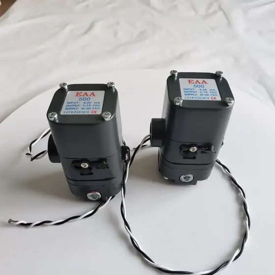
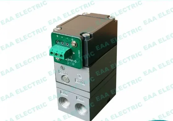
The 500X electro pneumatic transducer converts a current or voltage electrical input signal into a linearly proportional pneumatic output pressure. It functions as an I/P and E/P converter for industrial control loops where pneumatic control valves need to be driven directly by electrical control signals from a plant DCS or controller. Built as a direct meter without feedback, the unit produces high power aerodynamic output signals to operate valves and pneumatic instruments. It is designed for process control applications that require reliability and repeatability at an economical cost, serving as a replacement for standard Controlair type 500X pattern transducers.
| Model | 500X (EAA-500) |
|---|---|
| Type | I/P, E/P transducer (electro pneumatic converter) |
| Input signal | Current or voltage input signal |
| Output signal | Linearly proportional pneumatic output pressure |
| Operation mode | Direct (without feedback) |
| Temperature compensation | Automatic via internal thermistor |
| Adjustments | External zero and span |
| Housing colour | Black, blue, yellow or painted to customer requirement |
| Warranty | 18 months |
Why Buyers Specify This Model
- Converts electrical current or voltage signals directly into proportional pneumatic pressure
- Delivers high power aerodynamic output signals to drive pneumatic control valves directly
- Automatic temperature compensation via an internal thermistor keeps the output stable across temperature changes
- External zero and span adjustment devices make field calibration and routine maintenance fast
- Direct non-feedback operating principle provides high sensitivity and steady output loop performance
- Compact structure and light weight allow mounting directly on or near field valve actuators
- Economical replacement option for standard Controlair 500X pattern installations
Problems It Solves
- Pneumatic control valves cannot interpret direct electrical current or voltage control signals
- Field calibration takes too long when transducers lack accessible external adjustments
- Ambient temperature shifts cause output signal drift in uncompensated converters
- High replacement costs and long lead times for original brand I/P converters
- Actuators require higher aerodynamic power than standard low-power signal converters deliver
Application Scenarios
- Converting control room 4 to 20 mA or voltage signals to pneumatic pressure at the valve
- Driving pneumatic control valves that lack direct electronic signal input capability
- Retrofitting or replacing worn Controlair type 500X transducers in industrial plant lines
- Output control loops requiring repeatable pressure regulation without full feedback linkage
- Process skids where a compact and lightweight converter is needed to stroke pneumatic actuators
Who It Is For
- Plant instrument technicians replacing worn or failed Controlair type 500X transducers
- Valve and actuator assemblers who package I/P converters with pneumatic control valves
- EPC contractors procuring field instrumentation for industrial piping and skid builds
- Distributors stocking replacement electro pneumatic converters for local process plants
- OEMs requiring I/P and E/P transducers branded with custom paint and nameplates
Technical Features
- Linear conversion of electrical current or voltage input to pneumatic output pressure
- Direct operating mode without mechanical position feedback
- Internal thermistor circuit provides automatic temperature compensation
- External span and zero adjustment devices for field calibration
- High power aerodynamic pneumatic output signal
- Small footprint and light weight design for direct field installation
Materials and Construction
- Metal housing with painted protective finish
- Internal circuit board with temperature compensation thermistor
- Detailed material specifications are provided in the datasheet PDF
Dimensions and Connection Detail
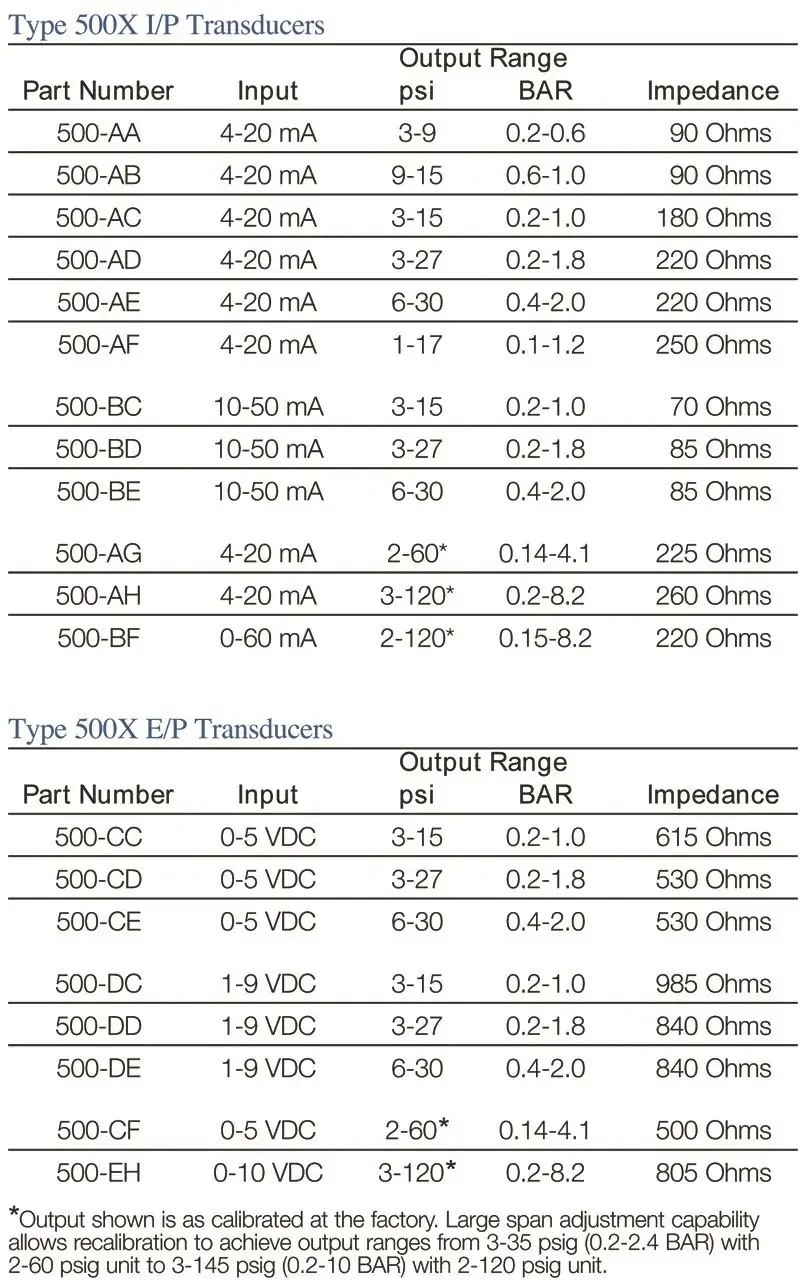
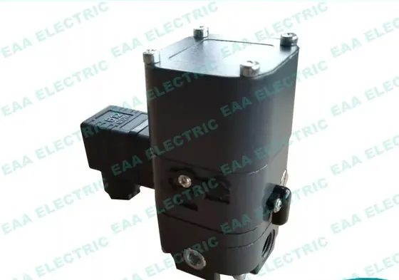
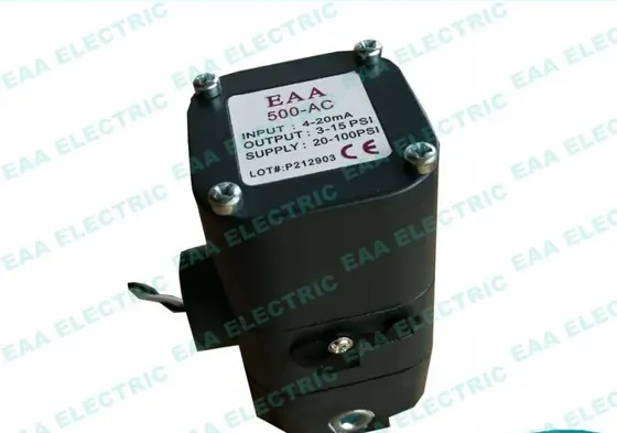
Reference image published with this model on the original catalogue. Confirm critical dimensions against the datasheet before machining a bracket.
Manufacturing and Quality Control
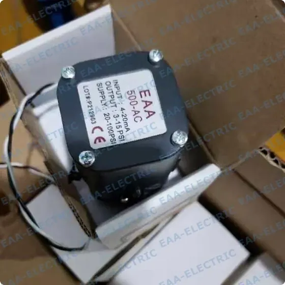
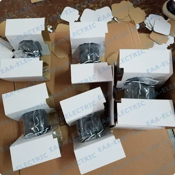
Every unit is calibrated and stroke tested before it is packed. We can film or photograph your units in the sample room or warehouse before they ship.
Manufacturing Steps
Housing preparation and surface finishing
Internal coil and electrical circuit board assembly
Integration of temperature compensation thermistor
Pneumatic nozzle and pilot stage assembly
Bench testing for pressure linearity across signal range
Zero and span calibration adjustment
Housing painting in customer specified colour and nameplate marking
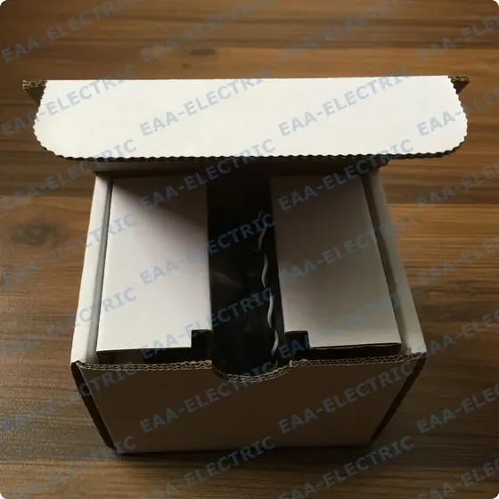
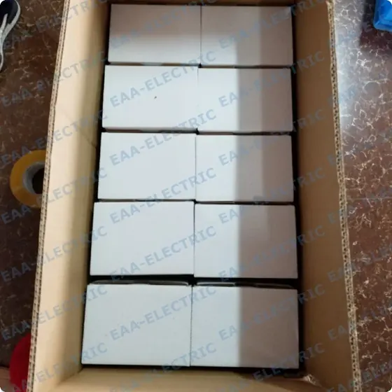
Carton packaging for shipment
Quality Control
- Every converter is calibrated and tested for proportional output response before packing
- Real product photos or video can be recorded in the sample room or warehouse prior to dispatch
- Faulty units within the 18 month warranty are replaced on photo or video evidence without return
- Urgent replacements ship immediately if plant operations are halted
Customisation Options
- Housing painted in custom colours including black, blue, yellow and others
- Customer brand logo and nameplate marking
- Newly designed shape modules developed to customer drawings
- Custom carton and packaging configurations
- Supply alongside matching pilot valves, limit switches, or pneumatic actuators
How It Compares With the Alternatives
| Valve positioner with mechanical feedback | The 500X regulates pneumatic pressure directly without stem feedback, making it simpler and lower cost where position feedback is not required |
|---|---|
| Uncompensated I/P converter | The 500X integrates an internal thermistor to automatically compensate for ambient temperature variations |
| Standard pneumatic signal booster | The 500X converts electrical input signals to air pressure, whereas a booster only amplifies an existing pneumatic signal |
Fitting and Setting Up This Model
General field procedure. Always follow the datasheet for the exact calibration sequence and any hazardous area requirements.
Mount the converter securely on the valve actuator yoke, bracket, or nearby pipe stand
Connect clean and dry instrument air supply to the pneumatic inlet port
Connect the pneumatic output port directly to the control valve actuator chamber
Wire the electrical current or voltage signal from the controller observing polarity
Apply minimum input signal and adjust the external zero screw until the specified base output is reached
Apply maximum input signal and adjust the external span screw to the target full-scale pressure
Cycle the input signal to verify linearity and repeat zero and span adjustments if necessary
500X Electro Pneumatic Transducer FAQ
What is the lead time for this converter?
Regular quantities normally ship in 2 to 3 days from stock. Large orders take 7 to 10 days.
Does the 500X include temperature compensation?
Yes. An internal thermistor is built into the converter circuit to automatically perform temperature compensation.
Can the zero and span be adjusted in the field?
Yes. The exterior housing features dedicated zero and span adjustment devices for convenient on-site maintenance.
Can we order these with our company branding and colours?
Yes. We can paint the housing in your required colour such as black, blue, or yellow, and apply your logo to the nameplate.
What warranty is provided on the 500X transducer?
We provide an 18 month warranty. If a unit fails, we replace it on photo or video evidence rather than repairing it.
Can I see actual product photos before the order ships?
Yes. We can provide real photos or videos of your finished units in our warehouse or sample room upon request.
Applications Cases and Guides
Related Case Photos
Related Products
Get A Price on This Model
Tell us the quantity, the actuator it goes on and the destination port. We come back with price, lead time and confirmation that the model matches your valve.