
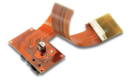
Assembled Rigid Flex Unit Linking A Connector Board To A Flex Tail
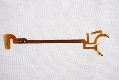
A populated assembly in which a component-loaded board with connectors and a power inductor is joined to a flexible tail terminated in a connector housing. One part carries both the electronics and the interconnect that would otherwise be a separate cable assembly.
What This Board Is
This is the format that removes a cable from the bill of materials. The rigid section carries the components, the flex tail does the interconnect, and there is no connector between the two because they are the same part. Everything that could go wrong at that joint has already been designed out. What is left is making sure the flex bends where it is meant to and that the terminated end mates properly.
- PCBA
- See specification
What You Get From This Build
- Removes one connector pair and one cable assembly from the finished product
- No intermediate joint means one fewer failure point in service and in test
- The flex tail folds into the housing, absorbing tolerance between two mounting faces
- Fabrication and assembly of both sections handled in one plant
Who Specifies This Board
- Camera and imaging module manufacturers
- Portable instrument builders with a hinged or folded architecture
- Medical device makers where every connector is a reliability risk
- Product teams trying to remove a cable assembly from a bill of materials
Four Failures This Build Is Designed Against
Each one is a real way this class of board goes wrong, and the tolerance or process decision that prevents it.
Connectors that intermittently disconnect in the field
A rigid flex part has no connector between the board and the tail because they are one etched circuit.
A cable assembly with its own part number and supplier
The interconnect becomes part of the board, so the cable, its connectors and its supplier all disappear.
Flex tails creasing where they were not meant to bend
Coverlay and stiffener placement fix where the part is free to bend and where it is held rigid.
Two mounting faces that are never quite where the drawing says
A folded flex tail takes up that tolerance without loading either joint.
Technical Specification
Product detail from the catalogue record, followed by the published process capability for the PCBA family. Anything the legacy catalogue did not record is marked TBC rather than filled in.
| Item | Technical specification |
|---|---|
| Product name | Rigid Flex Assembly With Connector Board |
| Legacy catalogue reference | FPCB-Assembly-2 |
| Product family | PCBA |
| Surface finish | See specification |
| Assembly technology | Surface mount, through-hole and mixed technology |
| Substrates assembled | Rigid FR4, aluminium metal core and flexible circuits |
| Bare board testing | Open and short test at 50 to 300 V before assembly |
| Component sourcing | Turnkey, consigned or mixed |
| Functional test | TBC — quoted against your test specification |
| Conformal coating | TBC — confirm the coating specification with your enquiry |
| Minimum order quantity | TBC — not recorded on the legacy catalogue |
| Lead time | TBC — confirmed per enquiry |
What The Board Is Made Of
| Material | Specification |
|---|---|
| Bare board | Rigid FR4, aluminium metal core or flexible circuit, fabricated in the same plant |
| Solder | Lead-free process, RoHS compliant |
| Components | Supplied by us on turnkey, or consigned by you |
| Stencil | Cut to the released paste layer of the same board revision |
| Packing | Packed on our own packing machines to your specification |
What Can Be Changed
- Turnkey, consigned or mixed component supply
- Rigid, aluminium or flexible substrates
- Mixed surface mount and through-hole builds
- Hand-fitted magnetics and mechanical parts
- Device programming, subject to confirmation
- Packing to your goods-in specification
How This Board Is Made
Eight stages on equipment sourced from the USA, Japan, Germany and Israel. Every stage listed runs inside our own plant.
Data and BOM review
Manufacturer part numbers checked and alternates agreed in writing before buying.
Bare board
Fabricated in the same plant and open and short tested at 50 to 300 V.
Stencil
Cut to the paste layer of the same released revision as the board.
Paste and placement
Solder paste printed, then surface mount devices placed.
Reflow
Profiled for the substrate, with flexible circuits carried flat in tooling.
Through-hole and manual
Connectors, magnetics and hand-fitted parts as separate operations with their own inspection.
Inspection
Assembled boards inspected before packing.
Packing
Packed on our own packing machines to your goods-in specification.
What Is Checked Before It Ships
- Bare board open and short tested at 50 to 300 V before any component is placed
- Stencil and board matched to the same released revision
- Post-reflow inspection before through-hole and manual operations
- Mechanical parts such as sockets and terminal blocks inspected as mechanical parts
- Functional test quoted and run against your own test specification
What The Plant Holds
- ISO 9001:2000. Quality management system certification recorded by the company. Current revision year available on request.
- ISO 14001:1996. Environmental management system certification recorded by the company.
- UL. Certification recorded by the company. File number available on request.
- RoHS and lead free. Listed in the company environmental policy alongside pollution prevention and resource reduction.
Certificate numbers, issue dates and current revision years are not published on the legacy site. Ask for copies with your enquiry and they will be sent with the quotation.
How It Compares With The Alternatives
Three boards from our own catalogue, side by side, so the trade-off is visible rather than argued.
| Assembly | Technology | Distinguishing feature | Best suited to |
|---|---|---|---|
| Rigid Flex Assembly With Connector Board | Rigid flex assembly | Connector housing | Cable replacement |
| FPCB Assembly With Antenna Coil | Flex assembly | Etched antenna | Tag and module products |
| 1 Layer Flex Ribbon Cable | Bare flex | Stiffened ends | Board to board ribbons |
What To Send With Your Enquiry
Four things that decide whether the quote comes back right the first time.
- Send the flat pattern with every bend line marked and the installed bend radius at each one.
- Give the connector housing part number and the termination method for the flex tail.
- Mark which regions are stiffened and which are free to flex.
- Say whether the assembly is delivered folded to its installed shape or flat.
Rigid Flex Assembly With Connector Board Questions
Is this a true rigid flex board?
Send your stack-up and we will confirm what construction it needs. Our flex capacity covers single, double and multilayer flexible circuits on PI, FR4 and PET.
How tight a bend radius can the flex take?
Bend radius depends on copper thickness and coverlay. Give the installed bend radius with the drawing and we will check it against the 9 to 70 micrometre copper range.
Can you terminate the flex tail with a connector housing?
Yes, as shown here. Give the connector part number and the crimp or solder termination you need.
Does the whole part get assembled in one pass?
The rigid section is populated in the normal way, and the tail and its termination are handled as separate operations with their own inspection.
Other Boards In The PCBA Family
Boards built on the same line, with the same tolerances, in a different configuration.
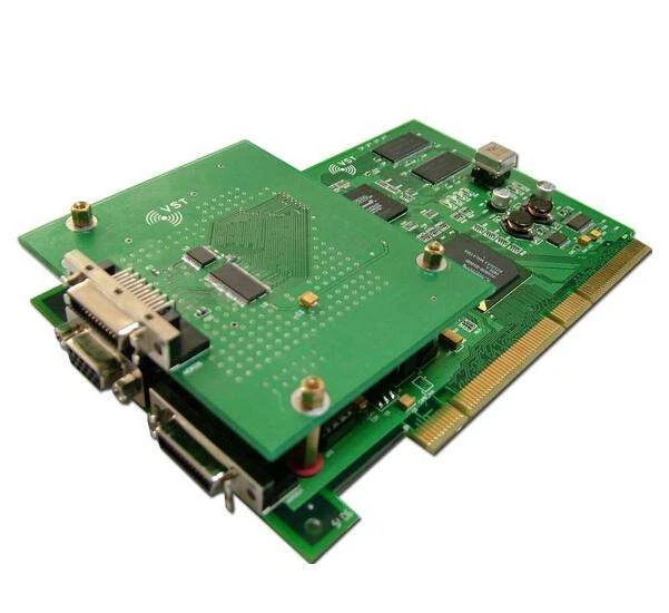
Assembled Interface Board With Serial Ethernet And Edge Connector
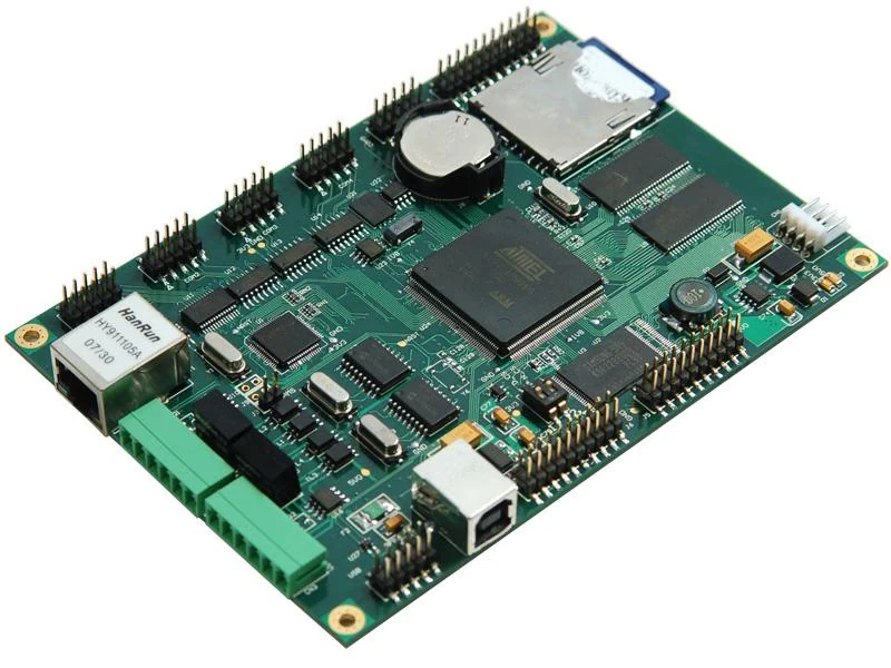
Assembled Embedded Controller With Microcontroller Ethernet And Storage
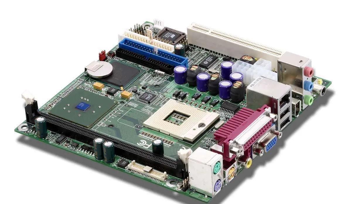
Assembled Motherboard With Expansion Slot And Rear Port Cluster
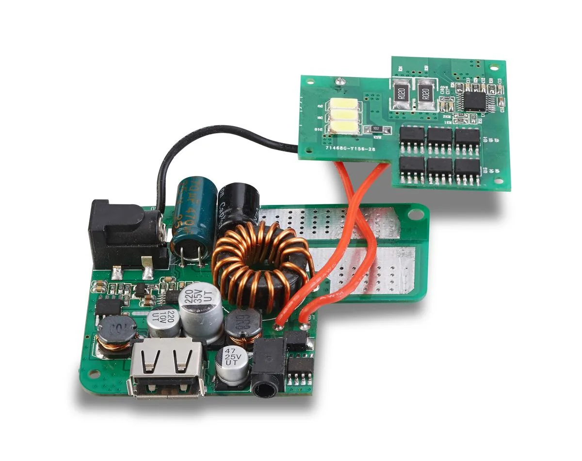
Assembled Power Converter With Toroidal Inductor And LED Output Board
Where This Board Is Used
The fields the legacy catalogue records for this class of board.
This Board In Context
Get Rigid Flex Assembly With Connector Board Priced Against Your Own Files
Send Gerber RS-274X with an NC drill file, or an ODB++ package, with the layer count, thickness, copper weight, surface finish and quantity. We check it against the published capability before quoting.