
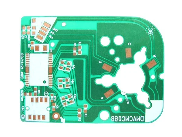
Single Sided Aluminium Board With OSP For Motor And Driver Circuits
A single sided aluminium-based board with an OSP finish and a profiled outline. The metal core pulls heat out of switching devices and into the chassis it is bolted to, which is what lets a driver stage run continuously in a sealed housing.
What This Board Is
Aluminium boards exist for one reason: FR4 is a thermal insulator and some circuits cannot afford that. The board shown is profiled to fit a motor housing, with wide copper pours around the power devices and mounting features cut into the outline. Thermal resistance of the laminate is measured at 1 degree Celsius per watt against an index value of 1.5, tested on a TO-220 package.
Aluminium cores are scrubbed, imaged and etched, then OSP roller coated rather than solder levelled.
- Aluminium PCB
- 1 layer
- OSP
- RoHS
What You Get From This Build
- Measured laminate thermal resistance of 1 °C/W lets power devices run cooler in the same enclosure
- The board itself becomes the heatsink, which removes a separate aluminium part from the bill of materials
- OSP is the lowest cost finish and leaves a flat, solderable copper surface
- Profiled outlines are routed on CNC routers to ±0.2 mm so the board drops into a shaped housing
Who Specifies This Board
- Motor drive and BLDC controller manufacturers
- Appliance makers putting electronics inside a sealed motor housing
- Power supply builders whose switching devices run hot in a small volume
- Automotive electronics suppliers working within a fixed thermal budget
Four Failures This Build Is Designed Against
Each one is a real way this class of board goes wrong, and the tolerance or process decision that prevents it.
Devices derating inside a sealed enclosure
A metal core conducts heat sideways into the mounting surface instead of trapping it under the package, which is what an FR4 board does.
A separate heatsink, pad and fixings per board
When the board is the heatsink, the thermal interface parts and their assembly labour disappear.
Round or profiled housings that a rectangular board will not fit
Outlines are CNC routed to ±0.2 mm, so the board can follow the housing rather than the housing following the board.
Copper shorting to the metal core
Dielectric strength of the laminate is above 1.3 kV/mm and insulation resistance sits at 10 to the power 12 ohms at normal condition.
Technical Specification
Product detail from the catalogue record, followed by the published process capability for the Aluminium PCB family. Anything the legacy catalogue did not record is marked TBC rather than filled in.
| Item | Technical specification |
|---|---|
| Product name | 1 Layer Aluminium PCB |
| Legacy catalogue reference | 1 Layer (MCPCB) |
| Product family | Aluminium PCB |
| Layer count | 1 layer |
| Surface finish | OSP |
| RoHS | RoHS compliant process, as recorded on the legacy catalogue |
| Maximum board size | 450 x 450 mm, single and double sided |
| Board thickness | 0.3 to 3.0 mm |
| Minimum track width | 0.15 mm |
| Minimum track space | 0.15 mm |
| Minimum hole size | 0.5 mm |
| Plated hole wall thickness | >0.02 mm |
| Plated hole diameter tolerance | ±0.05 mm for φ≤0.8 mm / ±0.08 mm for φ>0.8 mm |
| Non-plated hole diameter tolerance | ±0.05 mm for φ≤0.4 mm / ±0.1 mm for φ>0.4 mm |
| Hole position tolerance | ±0.05 mm |
| Outline tolerance | ±0.2 mm |
| Insulation resistance | 1012 Ω at normal condition |
| Dielectric strength | >1.3 kV/mm |
| Peel-off strength | 1.4 N/mm |
| Solder mask abrasion | >5H |
| Thermal stress | 265 °C for 5 seconds |
| Flammability rating | 94V-0 |
| Maximum working temperature | 125 °C |
| Bow and twist | <0.01 mm/mm |
What The Board Is Made Of
| Material | Specification |
|---|---|
| Base | Aluminium core, 0.3 to 3.0 mm total board thickness |
| Dielectric | Thermally conductive dielectric, >1.3 kV/mm dielectric strength |
| Copper | Peel-off strength 1.4 N/mm, tested at 2.2 N/mm to GJB1651 |
| Solder mask | Abrasion resistance >5H |
| Surface finish | OSP as standard |
What Can Be Changed
- Board thickness from 0.3 to 3.0 mm
- Single or double sided construction
- Profiled, round and strip outlines
- OSP as standard, other finishes on request
- Board size to 450 x 450 mm
- Assembly in the same plant
How This Board Is Made
Eight stages on equipment sourced from the USA, Japan, Germany and Israel. Every stage listed runs inside our own plant.
Core preparation
Aluminium core scrubbed on the scrubbing line to prepare the copper surface.
Imaging
Dry film laminated, exposed and developed to define the circuit.
Etching
Etching line removes the unwanted copper, then film stripping clears the resist.
Through holes
Double sided boards run the automatic PTH line to a wall above 0.02 mm.
Mask and legend
Solder mask and legend applied, with the dielectric verified for insulation resistance.
OSP finish
Applied on the WYD 0302 OSP roller coater.
Profiling
CNC routed to the finished outline at ±0.2 mm, including profiled and round shapes.
Flatness check
Bow and twist verified against the 0.01 mm per mm limit.
What Is Checked Before It Ships
- Dielectric strength verified above 1.3 kV/mm
- Insulation resistance at 1012 Ω at normal condition
- Thermal stress check at 265 °C for 5 seconds
- Bow and twist held below 0.01 mm per mm
- Laminate flammability rated FV-0 to GB/T4722 clause 26
What The Plant Holds
- ISO 9001:2000. Quality management system certification recorded by the company. Current revision year available on request.
- ISO 14001:1996. Environmental management system certification recorded by the company.
- UL. Certification recorded by the company. File number available on request.
- RoHS and lead free. Listed in the company environmental policy alongside pollution prevention and resource reduction.
Certificate numbers, issue dates and current revision years are not published on the legacy site. Ask for copies with your enquiry and they will be sent with the quotation.
How It Compares With The Alternatives
Three boards from our own catalogue, side by side, so the trade-off is visible rather than argued.
| Board | Layers or build | Finish | Best suited to |
|---|---|---|---|
| 1 Layer Aluminium PCB | 1 | OSP | Single sided power and driver circuits |
| 2 Layer Aluminium PCB | 2 | See specification | Circuits needing routing on both sides of the core |
| 2 Layer Rigid PCB | 2 | Lead-free HASL | Circuits with no significant heat to remove |
What To Send With Your Enquiry
Four things that decide whether the quote comes back right the first time.
- Give the maximum continuous power dissipated by each device so the copper area can be checked.
- Mark the mounting face and any area that must stay clear for a thermal interface.
- State the aluminium thickness required within the 0.3 to 3.0 mm range we build.
- OSP has a shorter shelf life than gold. Tell us your assembly date so we can time the build.
1 Layer Aluminium PCB Questions
How thick can the aluminium core be?
Board thickness runs from 0.3 to 3.0 mm, as published in our aluminium capacity table.
What is the maximum operating temperature?
125 degrees Celsius is the published maximum working temperature for the laminate.
How flat is an aluminium board?
Bow and twist is held below 0.01 mm per mm, which matters because the board is usually bolted to a flat face.
Why OSP instead of HASL?
OSP is flat, cheap and adequate for boards that are assembled soon after delivery. It is also the finish recorded for this board in our catalogue.
Other Boards In The Aluminium PCB Family
Boards built on the same line, with the same tolerances, in a different configuration.
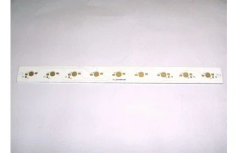
Single Sided Aluminium LED Bar With OSP Finish
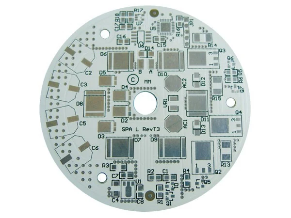
Double Sided Aluminium Board For Round Driver Modules
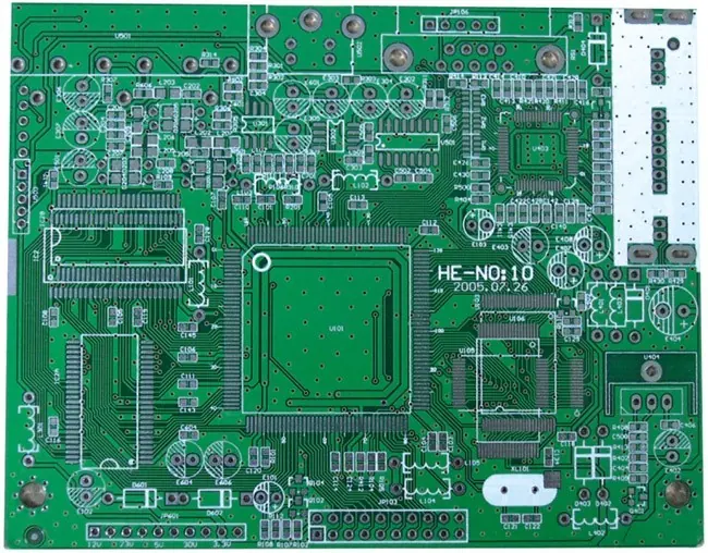
Double Sided FR4 Board With Lead Free HASL
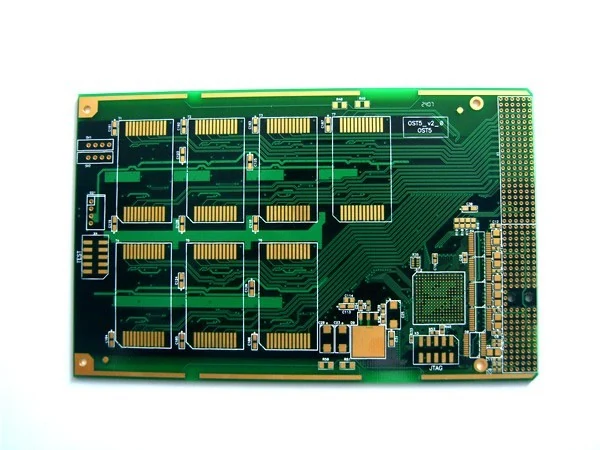
Four Layer Immersion Gold Board For Dense SMD Routing
Where This Board Is Used
The fields the legacy catalogue records for this class of board.
This Board In Context
Background Reading

Three surface finishes cover almost every board we build. Choosing between them is not a quality decision, it is a fitne...
When a board runs hot the usual fixes are a bigger heatsink or a bigger enclosure. A metal core board attacks the proble...
Get 1 Layer Aluminium PCB Priced Against Your Own Files
Send Gerber RS-274X with an NC drill file, or an ODB++ package, with the layer count, thickness, copper weight, surface finish and quantity. We check it against the published capability before quoting.