Thrust roller bearings exist to take axial load, and to take a great deal of it in a small height. They appear wherever a screw, a ram or a vertical shaft pushes: mill screw-downs, extruder gearboxes, oil well swivels, pulp refiners and machine tool tables.
Construction
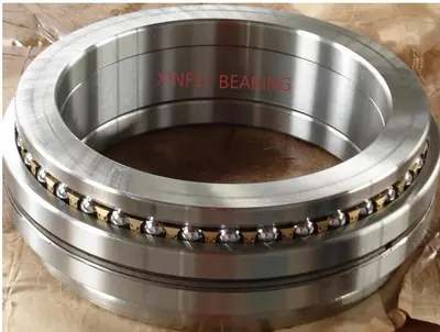
A thrust cylindrical roller bearing includes two flat hardened and ground steel washers with a cage retainer holding one or more controlled contour rollers between them. One washer seats on the shaft side, the other on the housing side, and the whole assembly is separable.
Thrust tapered designs consist of two thrust races, a set of tapered rollers and a cage. Because the rollers roll rather than skid across the race, this design can create up to 40 percent more capacity than cylindrical and spherical bearings with the same envelope dimensions.
The TP And T Series
Inch thrust series such as TP and T remain in wide use on mill and process equipment. They are identified by bore and outside diameter in inches rather than millimetres, and dimension tables normally give the load ratings Ca and Ca0 alongside the envelope. The thrust catalogue on this site lists these series with their dimensional data where the original tables recorded it.
Loading Rules
Thrust roller bearings must be axially loaded at all times. An unloaded thrust bearing lets the rollers skid, which produces smearing on the washer faces. Where load varies, a minimum load or a spring preload keeps the rollers rolling.
Radial load should not be applied. If the shaft needs radial support, a separate radial bearing should provide it and the thrust bearing should be allowed to float radially.
Seating And Flatness
Washer support surfaces must be flat and square to the shaft. A washer supported on a surface that is not flat concentrates the whole axial load on part of the roller path. Where housings cannot be machined to that standard, a spherical seating washer can be used to take out the error.