Choosing a bearing type is mostly a question of three things: which direction the load acts, how fast the shaft turns, and how much radial section you have between shaft and housing. Everything else follows from those answers. This guide compares the families supplied here so you can narrow the choice before looking at part numbers.
Load Direction Comes First
Radial load acts at right angles to the shaft. Axial or thrust load acts along it. Most real machines apply both, and the ratio between them eliminates most bearing types immediately.
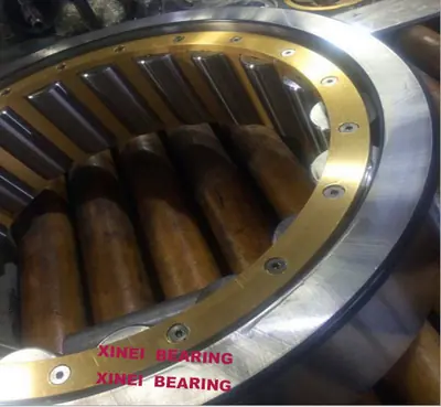
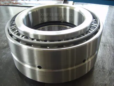
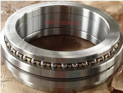
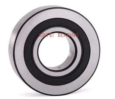
Deep groove ball bearings take radial load and a modest amount of axial load in either direction. Cylindrical roller bearings take much more radial load but, in the NU and N configurations, no axial load at all. Tapered and angular contact designs take combined load, with the split between radial and axial set by the contact angle. Thrust bearings take axial load only and must not be asked to carry radial load beyond a small fraction of the axial figure.
Then Speed
For a given bore, a ball bearing runs faster than a roller bearing, because point contact generates less friction and heat than line contact. Within roller bearings, a caged design runs faster than a full complement design, since the cage keeps rollers from rubbing against each other.
Cage material matters at the top of the speed range. Brass and steel cages tolerate higher temperature; polyamide runs quieter and lighter but has a temperature ceiling. This is covered in more detail in the cage material guide.
Then Section Height
If the space between shaft and housing is tight, needle roller bearings give the highest radial capacity per millimetre of section, which is why transmissions and planetary gear sets use them almost everywhere. Where the section is generous and the load is very high, a full complement cylindrical design such as the SL series fills the whole annulus with rollers and gives the highest rating available in that envelope, at the cost of speed.
Alignment And Deflection
Shafts deflect and housings are never perfectly in line. Spherical and toroidal designs accommodate misalignment internally. Cylindrical and tapered designs do not, and forcing them to run misaligned concentrates load at the roller ends, which shows up later as edge loading damage.
Quick Comparison
| Type | Radial | Axial | Speed | Misalignment |
|---|---|---|---|---|
| Deep groove ball | Medium | Low, both directions | High | Very limited |
| Angular contact ball | Medium | High, one direction | High | Very limited |
| Cylindrical roller | High | None or located | High | Limited |
| Full complement SL | Very high | None or located | Low | Limited |
| Tapered roller | High | High, one direction | Medium | Very limited |
| Needle roller | High for section | None | Medium | Limited |
| Spherical roller | Very high | Medium | Medium | Good |
| Thrust roller | None | Very high | Low to medium | Type dependent |