
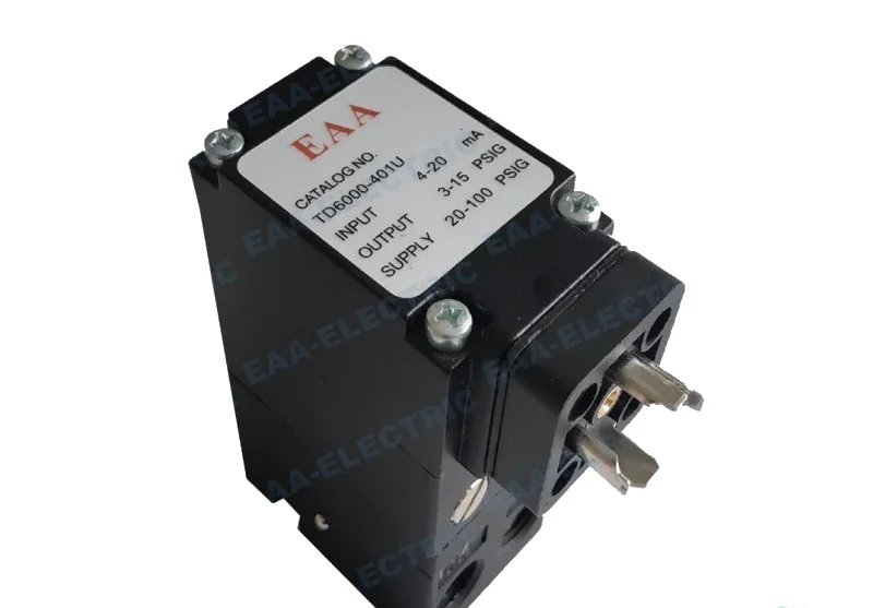
 Fairchild Type Transducer
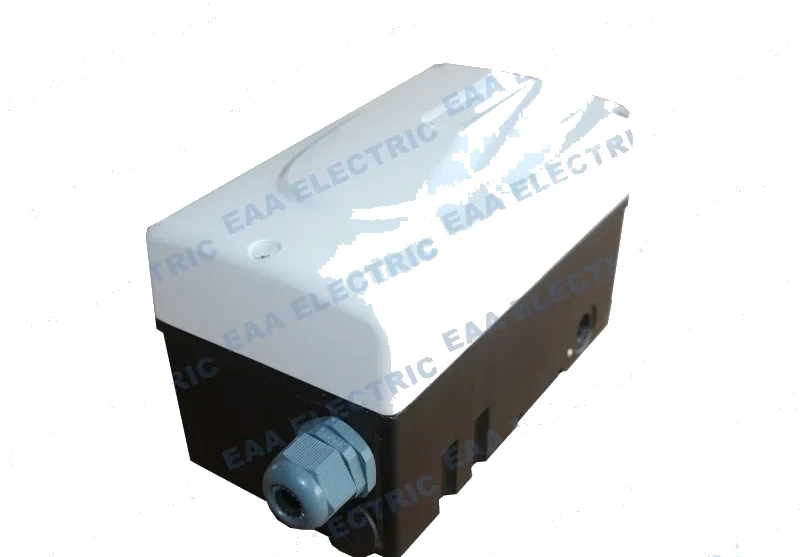 Flowserve Type Transducer
How An Electro Pneumatic Transducer Works
An electro pneumatic transducer is designed and works according to the principle of force balance. Follow the chain from the coil to the output and the one-to-one relationship between signal and pressure stops being a specification and becomes something you can reason about when a loop misbehaves.
The chain from current to pressure
There is a coil inside the instrument. When the current signal from the regulator or transmitter is sent to the coil, the coil and lever are displaced by the action of the internal permanent magnet. That displacement drives the baffle towards or away from the nozzle. Moving the baffle changes the nozzle back pressure, and that back pressure acts on the internal pneumatic power amplifier. The amplified pressure becomes the output of the converter.
Where the feedback comes from
The amplified pressure is not only sent to the output. Part of it is fed to the feedback bellows. The pressure delivered to the bellows produces a reverse displacement on the other end of the iron core through the force transmission of the lever. When that displacement and the input signal produce an electromagnetic torque balance, the input signal and the output pressure hold a one-to-one proportional relationship. That balance is the whole mechanism.
What the numbers mean
When the input signal changes from 4 mA DC to 20 mA DC, the output pressure of the I/P converter changes from 0.02 to 0.1 MPa. In the units most site drawings use, the converter receives 4-20 mA from the DCS and proportionally outputs 20-100 kPa, which is the pneumatic control signal for a pneumatic diaphragm regulating valve, a pneumatic valve positioner or another pneumatic instrument.
Where the zero adjustment fits
The zero adjustment mechanism sets the zero position of the converter, and the feedback bellows plays the feedback role. This is why zero and span are two separate adjustments rather than one: zero positions the mechanism, span limits how much current reaches the coil.
Why this matters in the field
If the output does not track the input, the fault is somewhere on this chain. A blocked nozzle, a contaminated amplifier or a damaged bellows each produce a different symptom. Knowing the order of the chain is what turns a replacement into a diagnosis.
Models This Applies To
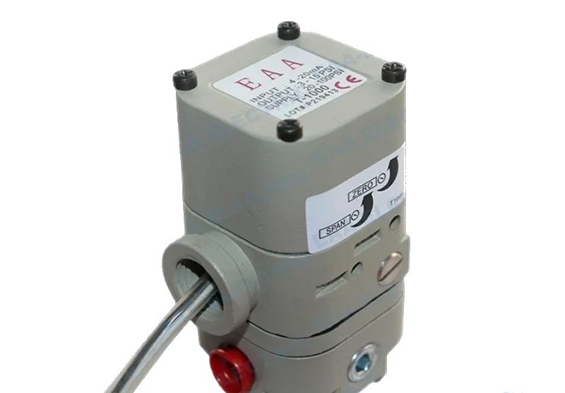 Marsh Bellofram Type Transducer
T1000 Electro Pneumatic Transducer
Force balance I/P transducer with a built-in volume booster, four build classes
View specifications →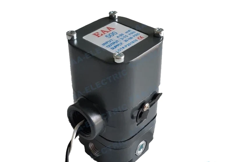 Controlair Type Transducer
500X Electro Pneumatic Transducer
Controlair pattern I/P transducer, 4-20 mA in, 3-15 to 3-120 psi out
View specifications →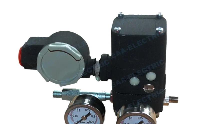 EPC Type Transducer
EPC1000 Electro Pneumatic Transducer
Direct moving E/P converter with a power amplifying relay, EAA's own EPC pattern
View specifications →Quick Answers
What output does 4-20 mA produce
0.02 to 0.1 MPa, which is 20 to 100 kPa, the standard pneumatic control signal.
Is an I/P transducer a closed loop device
It balances internally through the feedback bellows, but it has no feedback from the valve stem. That is the difference between a transducer and a valve positioner.
What does the zero adjustment actually move
It sets the zero position of the converter mechanism. The span adjustment is separate and limits the current through the coil.
Still Not Sure Which Instrument You Need
Send the loop details and we will point you at the model that fits, and tell you when a positioner would serve you better than a transducer.