
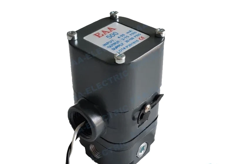
 Controlair Type Transducer
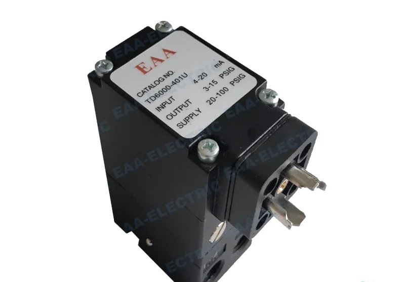 Fairchild Type Transducer
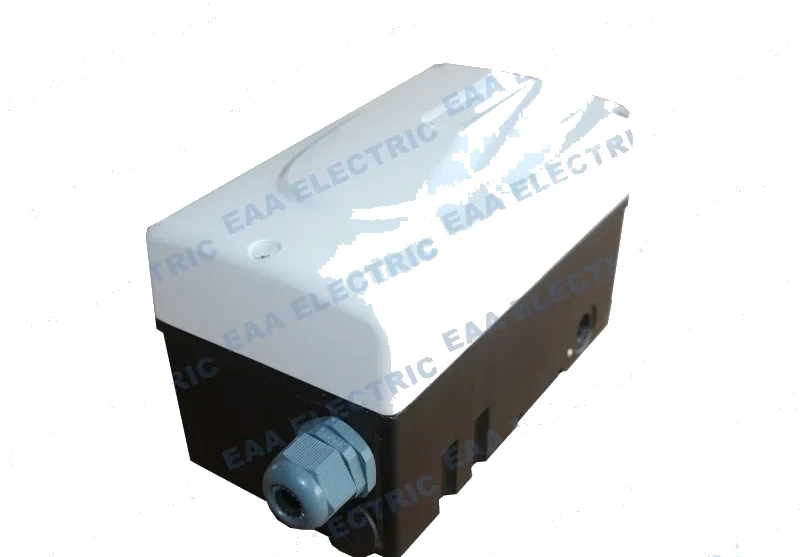 Flowserve Type Transducer
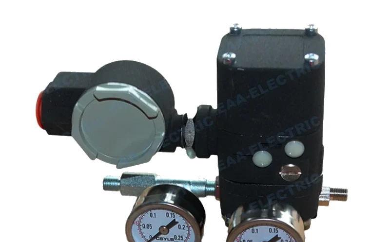 EPC Type Transducer
Calibrating An Electro Pneumatic Converter
A converter is a standard instrument and needs to be individually calibrated for accuracy. In actual use it is generally calibrated jointly with the regulating valve it is connected to, which reduces the workload and gives a result that reflects the pair rather than the instrument alone.
The instruments you need
A standard current signal generator, a standard pneumatic barostat, a 0.1 precision standard pressure gauge and a standard millimetre ruler. Nothing on that list is exotic, and attempting the job without the 0.1 class gauge is what makes calibrations disagree between technicians.
Making the connections
Connect the standard current signal generator to the converter junction box. Connect one end of the standard pneumatic barostat to the instrument air and the other to the instrument air inlet of the converter, and adjust the barostat output to a constant 140 kPa. Then connect the standard pressure gauge into the air path between the converter and the pneumatic control valve through the instrument air pipe.
Marking the starting point
Measure the stroke indicator of the control valve with the millimetre ruler and mark the initial position. Without that mark there is nothing to compare the later readings against.
Zero and span
Output 4 mA from the generator. Check that the standard pressure gauge is stable at 20 kPa and adjust it with the zero knob. Record the position of the control valve stem. Output 20 mA. Check that the gauge is stable at 100 kPa and adjust with the full-scale knob. Record the stem position. Repeat the two points until both hold.
Linearity and dead band
Test 12 mA, 8 mA and 16 mA in turn and observe the position corresponding to the linearity of the converter output and the opening of the regulating valve. Then observe the dead zone: use the signal generator to raise the current slowly from 4 mA, watch the valve stem until there is an obvious movement, and write down the current value and the pneumatic output at that point. Test the same thing in the reverse direction.
What to do with the record
Keep the dead band figure and the stem positions. The next time the loop is slow or hunting, comparing against that record is faster than starting a diagnosis from nothing.
Models This Applies To
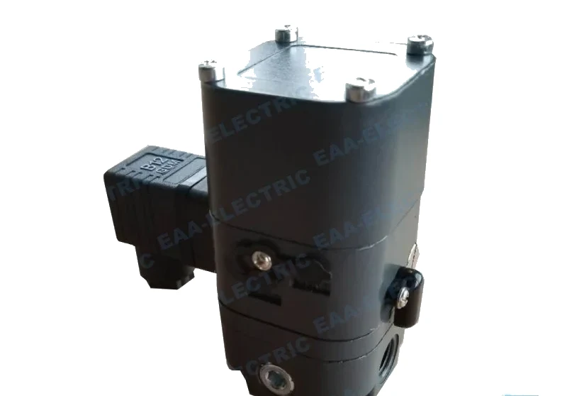 Controlair Type Transducer
500ACD Electro Pneumatic Transducer
500-AC range with a plug-in electrical termination
View specifications →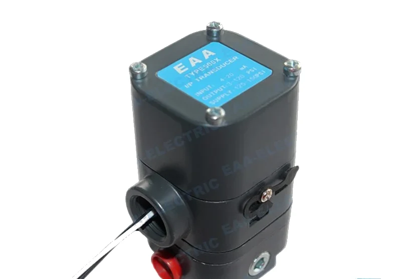 Controlair Type Transducer
500AC Electro Pneumatic Transducer
500-AC configuration, 4-20 mA in, 3-15 psi out, 180 ohms
View specifications →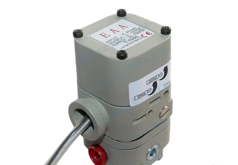 Marsh Bellofram Type Transducer
T1000 Electro Pneumatic Transducer
Force balance I/P transducer with a built-in volume booster, four build classes
View specifications →Quick Answers
What should the output be at 4 mA and 20 mA
20 kPa at 4 mA and 100 kPa at 20 mA, adjusted with the zero and full-scale knobs respectively.
What supply pressure is used during calibration
The barostat output is adjusted to a constant 140 kPa into the converter air inlet.
Why calibrate jointly with the valve
Because it reduces the workload and because the loop behaviour that matters is the behaviour of the converter and valve together.
Still Not Sure Which Instrument You Need
Send the loop details and we will point you at the model that fits, and tell you when a positioner would serve you better than a transducer.