
Tungsten Carbide Choke Beans And Flow Control Parts
Flow control parts sit in the worst place on the well: corrosive fluid, sand and impact all at once. Our grades of cemented carbide have been developed specifically to excel in those environments.
Product Overview
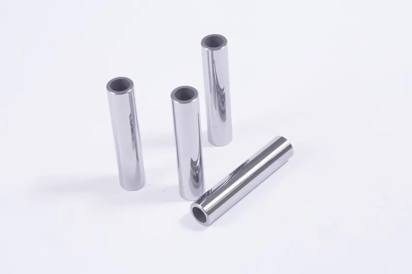
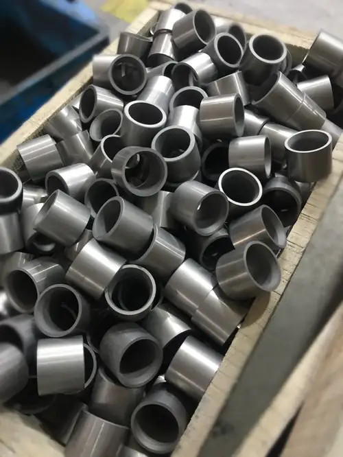
A choke bean is used in the positive choke valve to control flow. We supply the professional dimensional tungsten carbide liner that suits the choke bean of the Cameron type H2 Big John, where the body material is 410 stainless steel.
On one side of the choke manifold, calibrated choke beans control the flow rate through the fixed choke box. Each bean is a specific diameter, usually in graduations of one sixty-fourth of an inch, and is screwed into the choke box. The most common sizes in inches are 1/8, 3/16, 1/4, 5/16, 3/8, 7/16, 1/2, 9/16, 5/8, 3/4, 7/8, 1, 1-1/4 and 1-1/2, depending on the type of equipment used. Alongside beans we make seats, points and cages from the same grades.
Key Benefits
Grades Built For Aggressive Service
Our cemented carbide grades were developed to excel in environments that include corrosive, abrasive and impacting elements at the same time.
Calibrated In 1/64 Inch Steps
The published range runs from 3/64 to 64/64 inch bore, so the bean you need for a given flow rate is already a listed part number.
A Full Flow Control Set
Chokes, seats, points and cages come from one plant and one grade specification, so wear stays even across the assembly.
Application Scenarios
Where flow control carbide earns its place.
Positive Choke Valves
Calibrated beans screwed into a fixed choke box to set flow rate.
Choke Manifolds
Bean changes to step the flow rate up and down as the well is brought on.
Adjustable Chokes
Seats and points working as a pair to trim flow under pressure.
Cage Type Chokes
Cages that take the pressure drop across a set of ports rather than one orifice.
Well Testing
Bean sets carried to site so the flow rate can be stepped through a test programme.
Sand Laden Service
Duty where solids in the stream would cut a steel trim out in days.
Who It Is For
- Wellhead and choke valve manufacturers.
- Oilfield service companies maintaining choke manifolds.
- Distributors supplying replacement choke trim to operators.
- Well test companies that carry graduated bean sets.
Problems It Solves
- Steel beans that wash out and let the flow rate drift away from the recorded setting.
- Trim that has to be replaced every few weeks in sand laden service.
- Mismatched replacement beans that do not seat properly in an existing choke box.
- Long lead times when one bore size in a graduated set runs out.
Technical Features
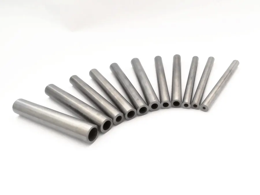
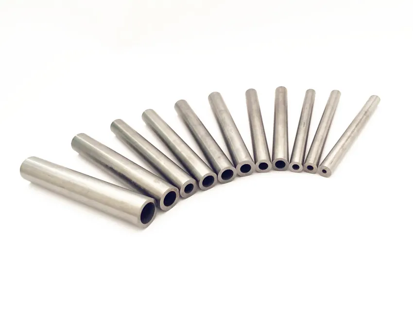
- Liner bore graduated in 1/64 inch steps, from 0.047 inch to 1.000 inch.
- Outside diameters of 0.375, 0.5, 0.625, 0.75, 0.875, 1, 1.125 and 1.25 inch.
- Outside diameter tolerance of +0/−0.254 mm on every size.
- Listed length of 149.225 mm with a ±0.381 mm tolerance.
- Dimensioned to suit the choke bean of the Cameron type H2 Big John, body material 410SS.
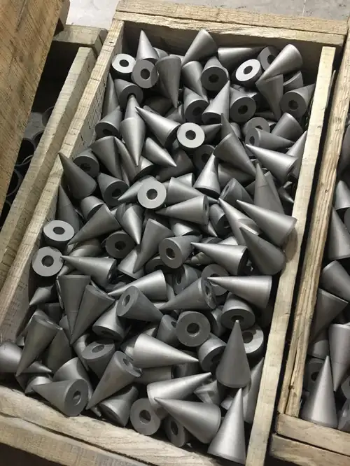
- Matching seats, points and cages made from the same grades.
- Customizable sizes outside the published table.
- Media covered by the range: oil, gas, water and sand.
Specifications
| Item no. | OD inch | ID inch | OD mm | OD tol. mm | ID mm | Length mm |
|---|---|---|---|---|---|---|
| CH-03-5875 | 0.375 | 0.047 | 9.525 | (+0/−0.254) | 1.191 | 149.225 (±0.381) |
| CH-04-5875 | 0.375 | 0.063 | 9.525 | (+0/−0.254) | 1.588 | 149.225 (±0.381) |
| CH-05-5875 | 0.375 | 0.078 | 9.525 | (+0/−0.254) | 1.984 | 149.225 (±0.381) |
| CH-06-5875 | 0.375 | 0.094 | 9.525 | (+0/−0.254) | 2.381 | 149.225 (±0.381) |
| CH-07-5875 | 0.375 | 0.109 | 9.525 | (+0/−0.254) | 2.778 | 149.225 (±0.381) |
| CH-08-5875 | 0.375 | 0.125 | 9.525 | (+0/−0.254) | 3.175 | 149.225 (±0.381) |
| CH-09-5875 | 0.5 | 0.141 | 12.7 | (+0/−0.254) | 3.572 | 149.225 (±0.381) |
| CH-10-5875 | 0.5 | 0.156 | 12.7 | (+0/−0.254) | 3.969 | 149.225 (±0.381) |
| CH-11-5875 | 0.5 | 0.172 | 12.7 | (+0/−0.254) | 4.366 | 149.225 (±0.381) |
| CH-12-5875 | 0.5 | 0.188 | 12.7 | (+0/−0.254) | 4.763 | 149.225 (±0.381) |
| CH-13-5875 | 0.5 | 0.203 | 12.7 | (+0/−0.254) | 5.159 | 149.225 (±0.381) |
| CH-14-5875 | 0.5 | 0.219 | 12.7 | (+0/−0.254) | 5.556 | 149.225 (±0.381) |
| CH-15-5875 | 0.5 | 0.234 | 12.7 | (+0/−0.254) | 5.953 | 149.225 (±0.381) |
| CH-16-5875 | 0.5 | 0.250 | 12.7 | (+0/−0.254) | 6.350 | 149.225 (±0.381) |
| CH-17-5875 | 0.625 | 0.266 | 15.875 | (+0/−0.254) | 6.747 | 149.225 (±0.381) |
| CH-18-5875 | 0.625 | 0.281 | 15.875 | (+0/−0.254) | 7.144 | 149.225 (±0.381) |
| CH-19-5875 | 0.625 | 0.297 | 15.875 | (+0/−0.254) | 7.541 | 149.225 (±0.381) |
| CH-20-5875 | 0.625 | 0.313 | 15.875 | (+0/−0.254) | 7.938 | 149.225 (±0.381) |
| CH-21-5875 | 0.625 | 0.328 | 15.875 | (+0/−0.254) | 8.334 | 149.225 (±0.381) |
| CH-22-5875 | 0.625 | 0.344 | 15.875 | (+0/−0.254) | 8.731 | 149.225 (±0.381) |
| CH-23-5875 | 0.625 | 0.359 | 15.875 | (+0/−0.254) | 9.128 | 149.225 (±0.381) |
| CH-24-5875 | 0.625 | 0.375 | 15.875 | (+0/−0.254) | 9.525 | 149.225 (±0.381) |
| CH-25-5875 | 0.75 | 0.391 | 19.05 | (+0/−0.254) | 9.922 | 149.225 (±0.381) |
| CH-26-5875 | 0.75 | 0.406 | 19.05 | (+0/−0.254) | 10.319 | 149.225 (±0.381) |
| CH-27-5875 | 0.75 | 0.422 | 19.05 | (+0/−0.254) | 10.716 | 149.225 (±0.381) |
| CH-28-5875 | 0.75 | 0.438 | 19.05 | (+0/−0.254) | 11.113 | 149.225 (±0.381) |
| CH-29-5875 | 0.75 | 0.453 | 19.05 | (+0/−0.254) | 11.509 | 149.225 (±0.381) |
| CH-30-5875 | 0.75 | 0.469 | 19.05 | (+0/−0.254) | 11.906 | 149.225 (±0.381) |
| CH-31-5875 | 0.75 | 0.484 | 19.05 | (+0/−0.254) | 12.303 | 149.225 (±0.381) |
| CH-32-5875 | 0.75 | 0.500 | 19.05 | (+0/−0.254) | 12.700 | 149.225 (±0.381) |
| CH-33-5875 | 0.875 | 0.516 | 22.225 | (+0/−0.254) | 13.097 | 149.225 (±0.381) |
| CH-34-5875 | 0.875 | 0.531 | 22.225 | (+0/−0.254) | 13.494 | 149.225 (±0.381) |
| CH-35-5875 | 0.875 | 0.547 | 22.225 | (+0/−0.254) | 13.891 | 149.225 (±0.381) |
| CH-36-5875 | 0.875 | 0.563 | 22.225 | (+0/−0.254) | 14.288 | 149.225 (±0.381) |
| CH-37-5875 | 0.875 | 0.578 | 22.225 | (+0/−0.254) | 14.684 | 149.225 (±0.381) |
| CH-38-5875 | 0.875 | 0.594 | 22.225 | (+0/−0.254) | 15.081 | 149.225 (±0.381) |
| CH-39-5875 | 0.875 | 0.609 | 22.225 | (+0/−0.254) | 15.478 | 149.225 (±0.381) |
| CH-40-5875 | 0.875 | 0.625 | 22.225 | (+0/−0.254) | 15.875 | 149.225 (±0.381) |
| CH-41-5875 | 1 | 0.641 | 25.4 | (+0/−0.254) | 16.272 | 149.225 (±0.381) |
| CH-42-5875 | 1 | 0.656 | 25.4 | (+0/−0.254) | 16.669 | 149.225 (±0.381) |
| CH-43-5875 | 1 | 0.672 | 25.4 | (+0/−0.254) | 17.066 | 149.225 (±0.381) |
| CH-44-5875 | 1 | 0.688 | 25.4 | (+0/−0.254) | 17.463 | 149.225 (±0.381) |
| CH-45-5875 | 1 | 0.703 | 25.4 | (+0/−0.254) | 17.859 | 149.225 (±0.381) |
| CH-46-5875 | 1 | 0.719 | 25.4 | (+0/−0.254) | 18.256 | 149.225 (±0.381) |
| CH-47-5875 | 1 | 0.734 | 25.4 | (+0/−0.254) | 18.653 | 149.225 (±0.381) |
| CH-48-5875 | 1 | 0.750 | 25.4 | (+0/−0.254) | 19.050 | 149.225 (±0.381) |
| CH-49-5875 | 1.125 | 0.766 | 28.575 | (+0/−0.254) | 19.447 | 149.225 (±0.381) |
| CH-50-5875 | 1.125 | 0.781 | 28.575 | (+0/−0.254) | 19.844 | 149.225 (±0.381) |
| CH-51-5875 | 1.125 | 0.797 | 28.575 | (+0/−0.254) | 20.241 | 149.225 (±0.381) |
| CH-52-5875 | 1.125 | 0.813 | 28.575 | (+0/−0.254) | 20.638 | 149.225 (±0.381) |
| CH-53-5875 | 1.125 | 0.828 | 28.575 | (+0/−0.254) | 21.034 | 149.225 (±0.381) |
| CH-54-5875 | 1.125 | 0.844 | 28.575 | (+0/−0.254) | 21.431 | 149.225 (±0.381) |
| CH-55-5875 | 1.125 | 0.859 | 28.575 | (+0/−0.254) | 21.828 | 149.225 (±0.381) |
| CH-56-5875 | 1.125 | 0.875 | 28.575 | (+0/−0.254) | 22.225 | 149.225 (±0.381) |
| CH-57-5875 | 1.25 | 0.891 | 31.75 | (+0/−0.254) | 22.622 | 149.225 (±0.381) |
| CH-58-5875 | 1.25 | 0.906 | 31.75 | (+0/−0.254) | 23.019 | 149.225 (±0.381) |
| CH-59-5875 | 1.25 | 0.922 | 31.75 | (+0/−0.254) | 23.416 | 149.225 (±0.381) |
| CH-60-5875 | 1.25 | 0.938 | 31.75 | (+0/−0.254) | 23.813 | 149.225 (±0.381) |
| CH-61-5875 | 1.25 | 0.953 | 31.75 | (+0/−0.254) | 24.209 | 149.225 (±0.381) |
| CH-62-5875 | 1.25 | 0.969 | 31.75 | (+0/−0.254) | 24.606 | 149.225 (±0.381) |
| CH-63-5875 | 1.25 | 0.984 | 31.75 | (+0/−0.254) | 25.003 | 149.225 (±0.381) |
| CH-64-5875 | 1.25 | 1.000 | 31.75 | (+0/−0.254) | 25.400 | 149.225 (±0.381) |
Item numbers, bores, outside diameters and length tolerances are taken from the GWM choke bean size chart. Sizes outside the table are customizable.
Materials
Every part is quoted against a grade from the GWM chart. Cobalt and nickel binder grades are both available.
Flow control grades carry enough binder to survive impact while keeping the hardness needed to resist sand. Medium grain grades such as YG6 and YG8 are the usual starting point for tubes and wear-resistant parts, and the non-magnetic YN6 and YN10 grades are available where the assembly has to work in a non-magnetic environment and where corrosion resistance matters.
Recommended starting grades for this product: YG6YG8YG10XYN6YN10
Manufacturing Process
- Step 01
Powder Blending
WC and binder powders are wet milled in ball mills to the grain size the grade calls for.
- Step 02
Forming
Extrusion, two-way pressing or oil pressing, depending on the section and the length of the part.
- Step 03
Sintering
Vacuum sintering and pressure sintering furnaces. Every order is sinter-HIPped.
- Step 04
Finishing
Blank CNC machining, centreless grinding and cryogenic treatment to the drawing.
Quality Control
- Incoming powder checked before milling so grain size and binder content match the grade.
- Density and hardness measured on sintered parts against the published grade values.
- Metallographic microscope used to check porosity and structure after sintering.
- Dimensions and tolerances verified against the drawing before packing.
Certifications
Chengdu Golden Wolfran Carbide is an ISO certificated enterprise. Copies of the current certificates are sent with the quotation on request, so ask us for the version that applies to your order.
Customization Options
We manufacture small and large scale carbide products to your drawing, supplied either as sintered or precision ground.
Bore Sizes To Order
Any bore outside the 3/64 to 64/64 inch table is quoted as a customizable size.
Other Choke Bodies
Send the choke box or the old bean and we will dimension a liner to fit it.
Complete Trim Sets
Beans, seats, points and cages supplied together in one grade so the set wears evenly.
Comparison With Other Products
| Part | Role in the valve | What kills it first |
|---|---|---|
| Choke bean | Fixed calibrated orifice screwed into the choke box | Bore erosion, which shifts the flow rate off the setting |
| Seat | Fixed half of an adjustable trim pair | Wash across the seat face where the jet lands |
| Point | Moving half that trims the opening | Tip erosion and impact damage on closing |
| Cage | Spreads the pressure drop across several ports | Port edge rounding under sand loading |
Use Guide
Reading The Part Number
Item CH-16-5875 means bore 16/64 inch, that is 0.250 inch or 6.350 mm. The bore step is the number in the middle of the item number, so a set from CH-08 to CH-24 covers 1/8 inch through 3/8 inch in sixteen even steps.
Matching The Outside Diameter
Outside diameter is grouped: bores from 3/64 to 8/64 inch use a 0.375 inch body, 9/64 to 16/64 use 0.5 inch, and so on up to 1.25 inch for the largest bores. Check the outside diameter against your choke box before ordering, because the bore alone does not identify the part.
Changing A Bean
Bleed down and confirm zero pressure before opening the choke box. Inspect the seat face in the box as well as the bean: if the box has washed, a new bean will not hold the setting either. Record the bore that went in, because the flow rate reading is only meaningful against a known bore.
Keeping A Set On Site
Well test work usually needs a graduated set rather than single sizes. Order the range in one batch so all the beans come from the same grade and the same production lot.
Frequently Asked Questions
What choke does your bean liner fit?
We supply the professional dimensional tungsten carbide liner which suits the choke bean of the Cameron type H2 Big John, where the body material is 410SS. Other choke bodies are quoted from your sample or drawing.
What bore sizes are available?
The published chart runs from 3/64 inch to 64/64 inch in 1/64 inch steps, which is CH-03-5875 through CH-64-5875. The most common sizes used are 1/8, 3/16, 1/4, 5/16, 3/8, 7/16, 1/2, 9/16, 5/8, 3/4, 7/8, 1, 1-1/4 and 1-1/2 inch, depending on the equipment.
How long are the liners?
The listed length is 149.225 mm with a tolerance of plus or minus 0.381 mm.
Do you make seats, points and cages as well?
Yes. Chokes, seats, points and cages are all part of the flow control range and are made from the same grades so the trim wears evenly.
Can you make a size that is not on the chart?
Yes, sizes are customizable. Send the bore, the outside diameter, the length and the choke body it has to fit.
What media are these parts intended for?
The range is intended for oil and gas, water and sand.
Related Products
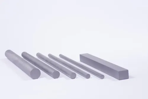
Tungsten Carbide Rods
Rotary tool blanks, solid and coolant channel
View product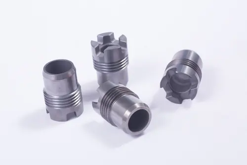
Tungsten Carbide Nozzles
Downhole, blast and threaded nozzles
View product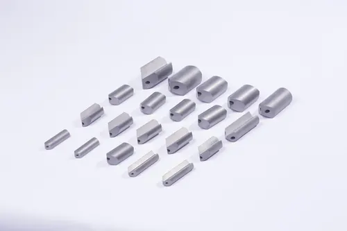
Tungsten Carbide Gun Drills
Deep hole drill blanks 10.5 to 35 mm
View product
Tungsten Carbide Inserts
Drill bit inserts and PDC substrates
View productRelated Applications
Related Downloads
Tell Us The Bore And The Choke Body
Bore size, outside diameter and the choke it fits is enough for a quotation. Graduated sets are quoted as one batch so the whole set comes from one production lot.