
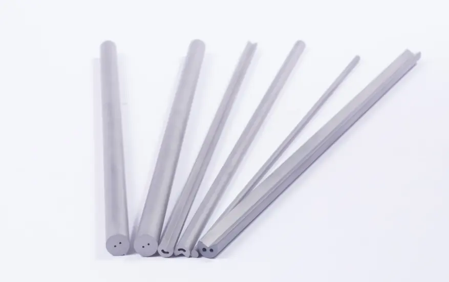
Rods With Two Straight Coolant Holes
Two parallel channels set on a bore circle, which is the standard configuration for a two flute solid carbide drill. Bore circle diameters run from 1.5 to 7.5 mm.
Overview
Twin straight hole rods are supplied from 6 to 26 mm diameter in 330 mm lengths. Hole diameter steps from 0.8 mm on the smallest rods through 1.0, 1.2 and 1.5 mm up to 2.0 mm from Ø17 upwards.
The bore circle, listed as TK, sets how far the two holes sit from the centreline: 1.5 mm at Ø6 to Ø8, 2.6 mm at Ø9 and Ø10, 3.6 mm from Ø11 to Ø13, 5 mm from Ø14 to Ø16, 6.2 mm from Ø17 to Ø22 and 7.5 mm from Ø23 to Ø26. Bore circle tolerance is one sided, tightening from +0/−0.2 mm to +0/−0.5 mm as the rod grows.
Why This Configuration
- Two channels, one per flute, on a controlled bore circle.
- Bore circle and eccentricity both published so flute break-through can be checked on paper.
- Covers the diameters used for most solid carbide two flute drills.
- Ground to H6 or supplied as sintered with grinding stock.
Specifications
| Part no. | Diameter mm | Unground tol. mm | Ground tol. | Length mm | Hole dia. mm | Hole tol. mm | Bore circle TK mm | TK tol. mm | Eccentricity mm |
|---|---|---|---|---|---|---|---|---|---|
| GCS1060330080015 | 6 | +0.30/+0.50 | H6 | 330 | 0.8 | ±0.1 | 1.5 | (+0/−0.2) | 0.15 |
| GCS1070330080015 | 7 | +0.30/+0.60 | H6 | 330 | 0.8 | ±0.1 | 1.5 | (+0/−0.2) | 0.15 |
| GCS1080330100015 | 8 | +0.30/+0.60 | H6 | 330 | 1 | ±0.15 | 1.5 | (+0/−0.3) | 0.15 |
| GCS1090330100026 | 9 | +0.30/+0.60 | H6 | 330 | 1 | ±0.15 | 2.6 | (+0/−0.3) | 0.2 |
| GCS1100330100026 | 10 | +0.30/+0.60 | H6 | 330 | 1 | ±0.15 | 2.6 | (+0/−0.3) | 0.2 |
| GCS1110330120036 | 11 | +0.30/+0.60 | H6 | 330 | 1.2 | ±0.15 | 3.6 | (+0/−0.3) | 0.28 |
| GCS1120330120036 | 12 | +0.30/+0.60 | H6 | 330 | 1.2 | ±0.15 | 3.6 | (+0/−0.3) | 0.3 |
| GCS1130330120036 | 13 | +0.30/+0.70 | H6 | 330 | 1.2 | ±0.15 | 3.6 | (+0/−0.3) | 0.34 |
| GCS1140330150050 | 14 | +0.30/+0.70 | H6 | 330 | 1.5 | ±0.15 | 5 | (+0/−0.3) | 0.37 |
| GCS1150330150050 | 15 | +0.30/+0.70 | H6 | 330 | 1.5 | ±0.15 | 5 | (+0/−0.3) | 0.4 |
| GCS1160330150050 | 16 | +0.30/+0.70 | H6 | 330 | 1.5 | ±0.15 | 5 | (+0/−0.3) | 0.4 |
| GCS1170330200062 | 17 | +0.30/+0.80 | H6 | 330 | 2 | ±0.20 | 6.2 | (+0/−0.3) | 0.47 |
| GCS1180330200062 | 18 | +0.30/+0.80 | H6 | 330 | 2 | ±0.20 | 6.2 | (+0/−0.3) | 0.5 |
| GCS1190330200062 | 19 | +0.30/+0.80 | H6 | 330 | 2 | ±0.20 | 6.2 | (+0/−0.3) | 0.5 |
| GCS1200330200062 | 20 | +0.30/+0.80 | H6 | 330 | 2 | ±0.20 | 6.2 | (+0/−0.4) | 0.5 |
| GCS1210330200062 | 21 | +0.30/+0.80 | H6 | 330 | 2 | ±0.20 | 6.2 | (+0/−0.4) | 0.5 |
| GCS1220330200062 | 22 | +0.30/+0.80 | H6 | 330 | 2 | ±0.20 | 6.2 | (+0/−0.4) | 0.5 |
| GCS1230330200075 | 23 | +0.30/+0.80 | H6 | 330 | 2 | ±0.20 | 7.5 | (+0/−0.4) | 0.5 |
| GCS1240330200075 | 24 | +0.30/+0.80 | H6 | 330 | 2 | ±0.20 | 7.5 | (+0/−0.5) | 0.5 |
| GCS1250330200075 | 25 | +0.30/+0.80 | H6 | 330 | 2 | ±0.20 | 7.5 | (+0/−0.5) | 0.5 |
| GCS1260330200075 | 26 | +0.30/+0.80 | H6 | 330 | 2 | ±0.20 | 7.5 | (+0/−0.5) | 0.5 |
Materials
Any grade in the GWM chart can be pressed in this configuration. For cutting tools the usual choices are GW10U, GW20U and GW30U for general drilling, and GW40U or GW45U where the finished tool has to work on hard steels, stainless steel or titanium.
GW10UGW20UGW30UGW40UGW45UYG6XYG10X
Manufacturing Process
- Step 01
Powder Blending
WC and binder powders are wet milled in ball mills to the grain size the grade calls for.
- Step 02
Forming
Extrusion, two-way pressing or oil pressing, depending on the section and the length of the part.
- Step 03
Sintering
Vacuum sintering and pressure sintering furnaces. Every order is sinter-HIPped.
- Step 04
Finishing
Blank CNC machining, centreless grinding and cryogenic treatment to the drawing.
- Incoming powder checked before milling so grain size and binder content match the grade.
- Density and hardness measured on sintered parts against the published grade values.
- Metallographic microscope used to check porosity and structure after sintering.
- Dimensions and tolerances verified against the drawing before packing.
Frequently Asked Questions
What is the TK dimension?
TK is the bore circle diameter, which is the circle the two coolant holes sit on. On a 20 mm rod it is 6.2 mm with a tolerance of +0 to minus 0.4 mm.
Why is the bore circle tolerance one sided?
The holes are allowed to move inward but not outward, which protects the wall thickness between the hole and the flute.
What diameters are covered?
6 to 26 mm as listed. Other diameters are made to order.
Can the holes be made larger than the table shows?
Hole diameter, bore circle and rod diameter are all quoted from your drawing when you need something outside the standard table.
Related Products
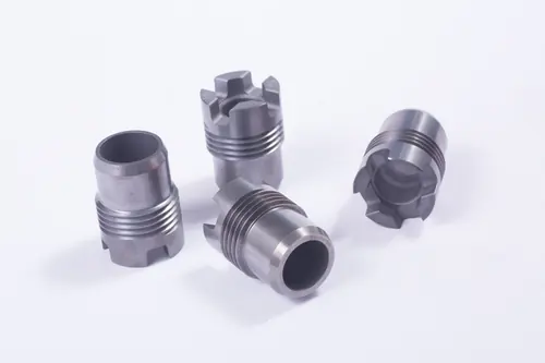
Tungsten Carbide Nozzles
Downhole, blast and threaded nozzles
View product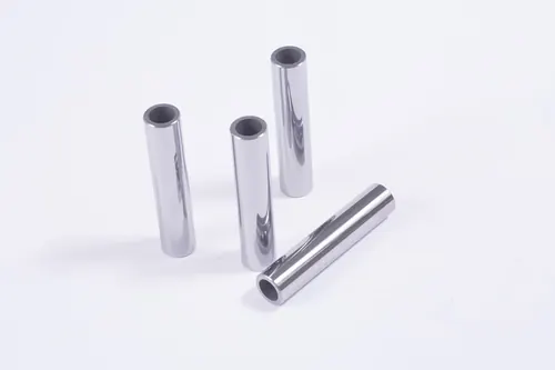
Tungsten Carbide Choke Beans
Flow control liners, seats, points, cages
View product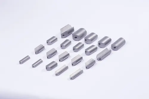
Tungsten Carbide Gun Drills
Deep hole drill blanks 10.5 to 35 mm
View product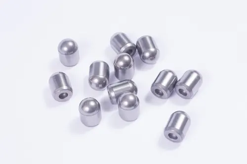
Tungsten Carbide Inserts
Drill bit inserts and PDC substrates
View productOther Rod Types
Related Articles
Related Applications
Send The Rod Drawing
Diameter, length, hole geometry and grade. Quotations go out in 24 hours or less.