
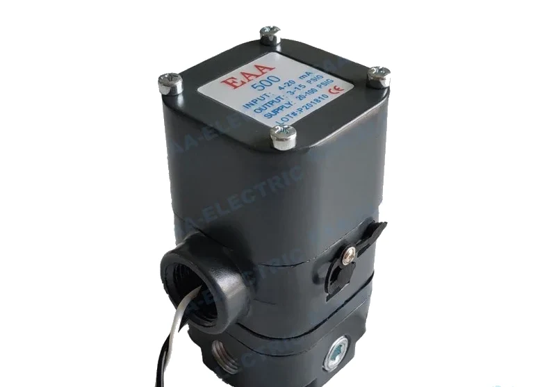
 Controlair Type Transducer
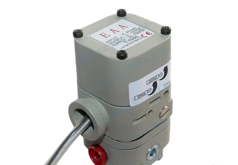 Marsh Bellofram Type Transducer
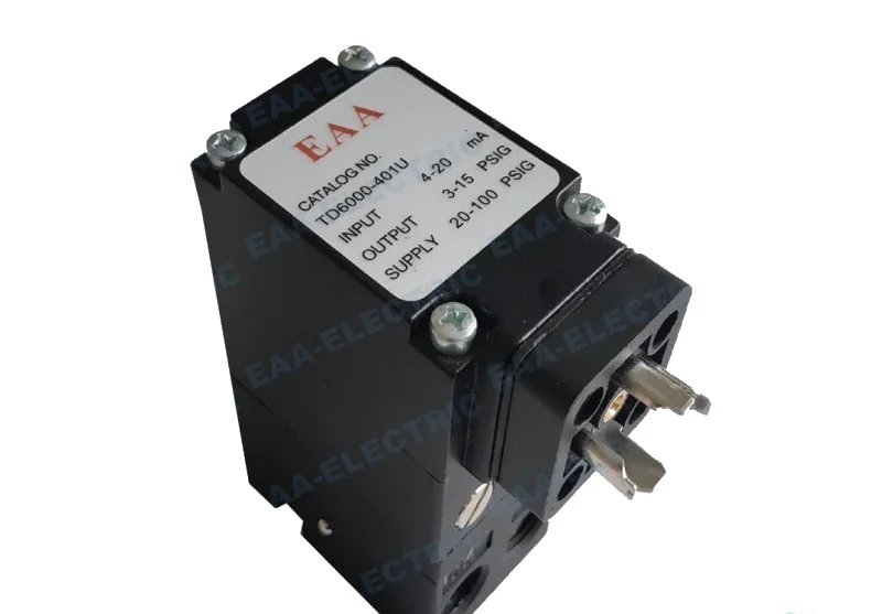 Fairchild Type Transducer
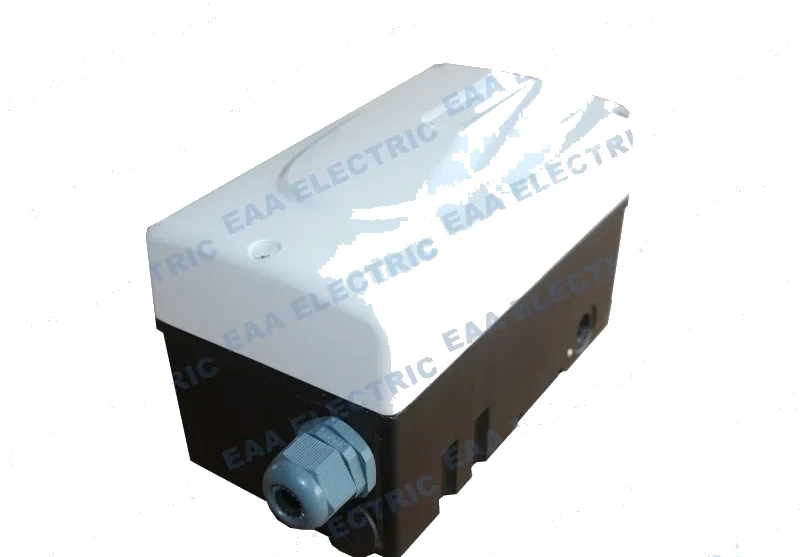 Flowserve Type Transducer
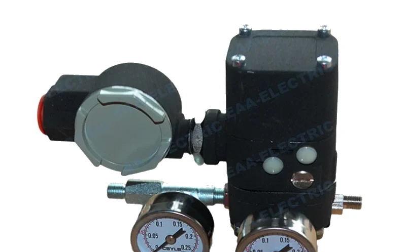 EPC Type Transducer
Selecting An Electro Pneumatic Converter For A Control Valve
An electro pneumatic converter converts 4-20 mA into a 20-100 kPa pneumatic signal. That sounds like it will suit any valve, and it will not. The converter has to be selected against the site conditions, and getting that wrong produces a valve that never reaches full travel.
The spring range decides the selection
The converter should be used according to the site conditions, which means the spring compression coefficient of the pneumatic control valve connected to it has to be 20-100 kPa. If the converter is used beyond this range, the full-open and full-close actions of the regulating valve cannot be realised.
Why this is different from a positioner
A valve positioner takes feedback from the stem and will drive towards the demanded position within its capability. A converter has no such feedback. It produces a pressure proportional to the signal and nothing more, so the electrical converter must be carefully selected rather than adjusted into place afterwards.
Air circuit pretreatment
Just as an audio amplifier has requirements for its power supply voltage, the converter has requirements for the instrument air that powers it. The instrument air pressure entering the converter is required to be stable near 0.14 MPa.
Where the filter regulator belongs
The air inlet of the converter should be equipped with an air filter and a pressure reducing device, so that the instrument air entering the converter is constant and free of impurities. Upstream conditioning at the header is not a substitute: the pressure has to be right at the instrument.
A selection checklist
Confirm the input signal, confirm the actuator spring compression coefficient, choose the output range from the published table or coding system, choose the electrical termination the installation uses, confirm the area classification, and fit a filter regulator at the inlet.
Models This Applies To
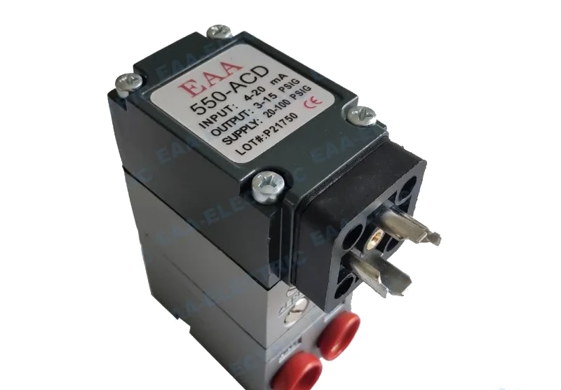 Controlair Type Transducer
550X Electro Pneumatic Transducer
Miniature EAA-550 series electronic pressure regulator, coded ordering
View specifications →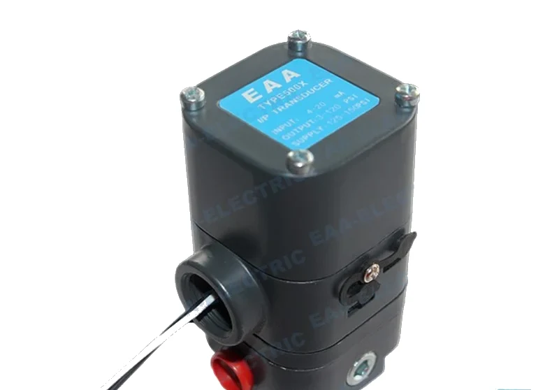 Controlair Type Transducer
500AC Electro Pneumatic Transducer
500-AC configuration, 4-20 mA in, 3-15 psi out, 180 ohms
View specifications →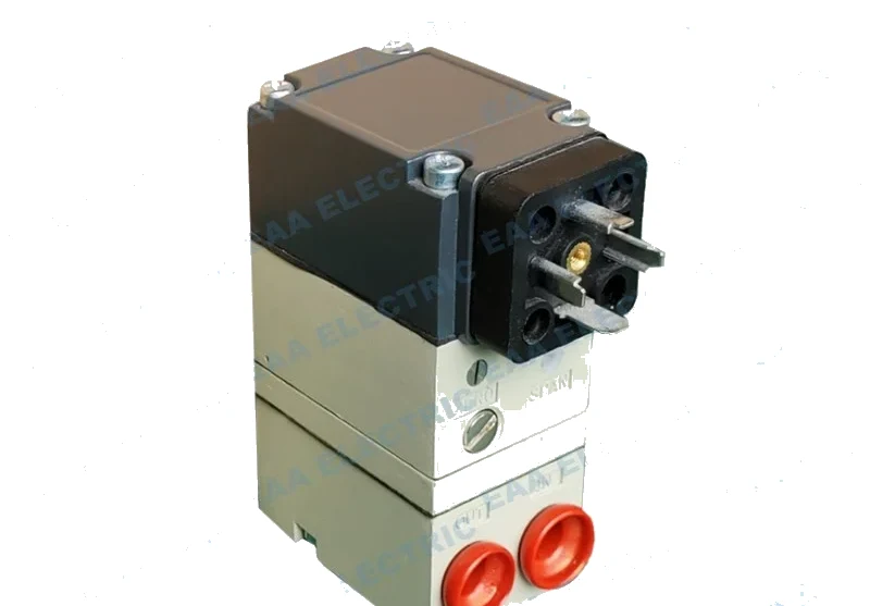 Marsh Bellofram Type Transducer
T1500 Electro Pneumatic Converter
Zero based T1500 build, 0-15 to 0-120 psig, regulates down to 0 psig
View specifications →Quick Answers
What spring range does a standard converter suit
20-100 kPa. Outside that range the regulating valve cannot achieve full-open and full-close actions.
What air pressure does the converter need
Instrument air stable near 0.14 MPa, delivered through an air filter and pressure reducing device fitted at the converter inlet.
What do I do if the spring is outside 20-100 kPa
Change the output range rather than the calibration. The 550 coding system and the 500X selection table both list ranges above and below the standard.
Still Not Sure Which Instrument You Need
Send the loop details and we will point you at the model that fits, and tell you when a positioner would serve you better than a transducer.