
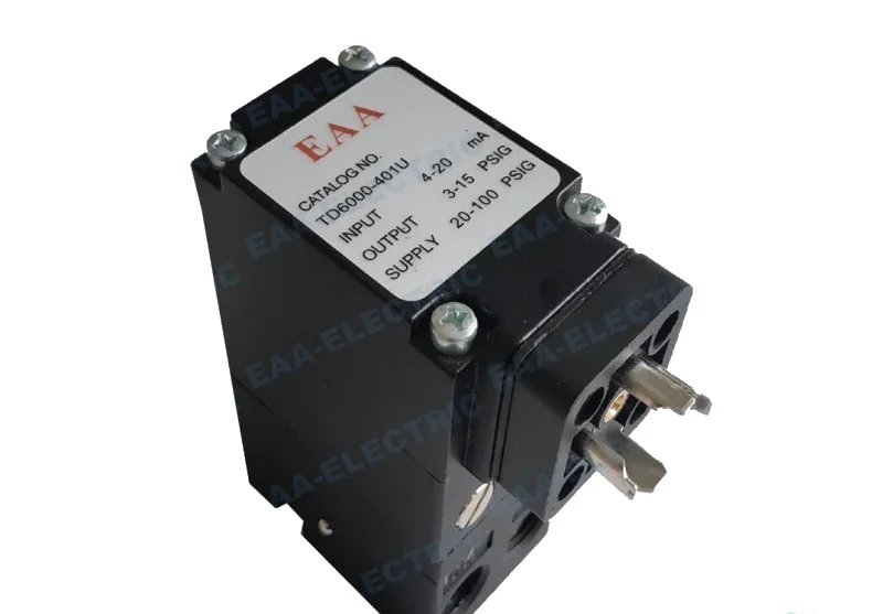
 Fairchild Type Transducer
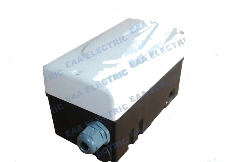 Flowserve Type Transducer
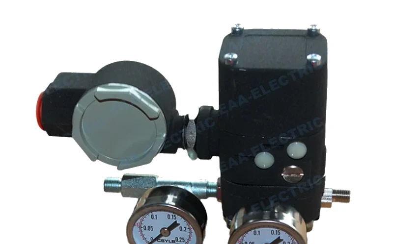 EPC Type Transducer
Principle And Composition Of An I/P Transducer
Pneumatic instrumentation feels unfamiliar in a highly integrated electronic era, and people assume there is no way to analyse it. In fact the principle is the same as an electronic circuit. Pneumatic signal control is regulating a high-power compressed air flow, and the electro pneumatic transducer is developed from the classic pneumatic instrument principle.
The two core components
The core components of the instrument are the nozzle baffle mechanism and the pneumatic power amplifier. Everything else in the housing exists to support those two: to hold them in position, to adjust them and to keep dirt out of them.
Electromagnetic change becomes spatial change
The method of electrical conversion is to turn an electrical signal into a physical displacement of a mechanical part through electromagnetic conversion. That mechanical part is the baffle in the nozzle baffle mechanism.
What the baffle actually is
The baffle is a solid thin metal disc in the middle. The other side of the disc is designed as a thin metal coil structure, convex outside and hollow inside. The metal coil passes through a strong magnetic permanent magnet cylinder. The current in the coil is the 4-20 mA control signal from the control room. As the current value changes, the attraction of the strong magnet changes, and that causes a physical displacement of the disc baffle which is integrated with the metal coil.
From displacement to usable pressure
Displacing the baffle restricts or opens the air flow through the nozzle, which changes the nozzle back pressure. That back pressure is small and cannot drive anything on its own, which is what the pneumatic power amplifier is for: it turns a pilot pressure into an output with enough flow behind it to move a final control element.
Why this design keeps being used
It has very few moving parts, no electronics in the air path, and it can be adjusted with two screws on the front face. On the T1000 and T1500 patterns a thermistor circuit in series with the coil adds temperature compensation, which removes the main remaining source of drift.
Models This Applies To
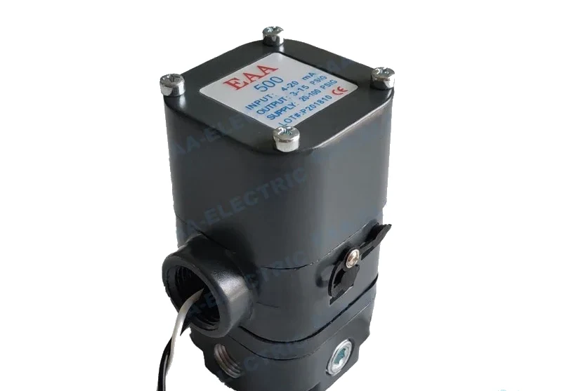 Controlair Type Transducer
500X Electro Pneumatic Transducer
Controlair pattern I/P transducer, 4-20 mA in, 3-15 to 3-120 psi out
View specifications →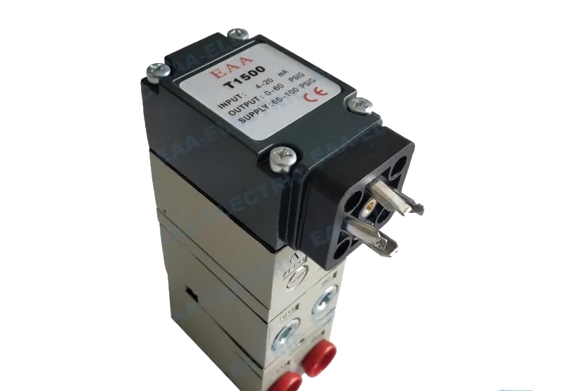 Marsh Bellofram Type Transducer
T1500 Electro Pneumatic Transducer
Compact force balance transducer, manifold mountable, 3-15 to 6-30 psig
View specifications →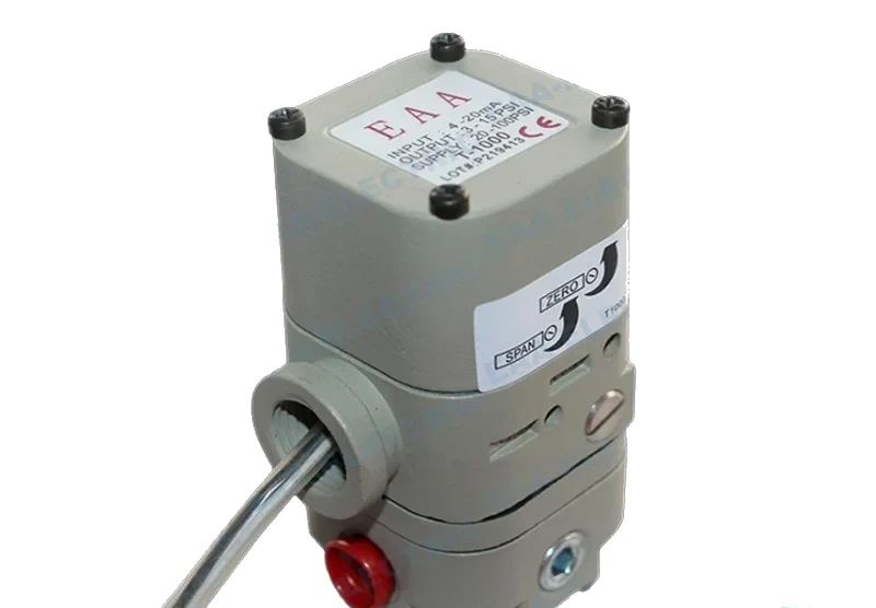 Marsh Bellofram Type Transducer
T1000 Electro Pneumatic Transducer
Force balance I/P transducer with a built-in volume booster, four build classes
View specifications →Quick Answers
What are the core components of an electro pneumatic transducer
The nozzle baffle mechanism and the pneumatic power amplifier.
Why is the baffle built as a coil and a disc together
So that current through the coil, sitting in the field of a permanent magnet cylinder, displaces the disc directly. The electrical change becomes a spatial change in one part.
What provides temperature compensation
On the force balance patterns, a thermistor circuit in series with the coil.
Still Not Sure Which Instrument You Need
Send the loop details and we will point you at the model that fits, and tell you when a positioner would serve you better than a transducer.