
Crown Gear
Grown gears are manufactured to customer drawings across module 0.5 to module 10 for angular driveline configurations. NOWARUN machines them from carbon steel, alloy steel, polymer, or foreign standard grades to precision levels between DIN 4 and DIN 10. Cutting methods include hobbing, shaping, shaving, and grinding, supported by in-house heat treatment and plating to match your equipment requirements.
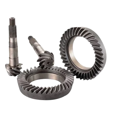
Published Data for Crown Gear
Every value below is taken from NOWARUN's own specification for this part.
| Module | 0.5 to 10 |
|---|---|
| Gear Precision | DIN 4 to DIN 10 |
| Processes | Hobbing, shaving, grinding, shaping |
| Heat Treatment | Carburizing, carbonitriding, QT, quenching, tempering, induction hardening |
| Surface Treatment | Various plating |
| Material | Carbon steel, alloy steel, polymer, customized foreign standard grades |
| Packaging | PP bag, carton, crate, box or according to customer requirements |
| Origin | Hangzhou, Zhejiang, China |
Key Benefits
- Gear precision from DIN 4 to DIN 10 allows selection based on specific operating noise and backlash targets
- Module coverage from 0.5 to 10 supports both compact assemblies and heavy industrial drive mechanisms
- Multiple tooth cutting processes including hobbing, shaping, shaving, and grinding ensure accurate profiles
- Heat treatments such as carburizing, induction hardening, and QT provide wear resistance on tooth flanks
- Available in carbon steel, alloy steel, polymer, and international equivalent steel grades
- Manufactured strictly to drawing rather than limited to off-the-shelf catalogue dimensions
Problems It Solves
- Catalogue gears do not match proprietary shaft bores, mounting faces, or keyway layouts
- Excessive gear wear occurs when untempered or incorrectly case-hardened teeth face heavy shock loading
- Mismatched gear tooth geometry causes running vibration, premature tooth pitting, and driveline noise
- Procuring gears across separate machining, heat treatment, and surface finishing suppliers increases lead time risk
Who It Is For
- Mechanical design engineers developing custom bevel drive transmissions with non-standard shaft configurations
- Procurement specialists sourcing replacement gear sets cut to DIN standards rather than generic commercial stock
- Machinery builders requiring matched gear pairs with controlled surface hardness and ground flanks
- OEM equipment manufacturers looking to contract gear cutting across multiple steel and polymer grades
Application Scenarios
- Right-angle transmission units for agricultural machinery exposed to cyclic field loads
- Wood processing machinery gearboxes requiring hardened bevel teeth operating near cutting spindles
- Drivelines in machine construction where custom shaft bores and mounting distances are required
- Mining and aggregate equipment needing tough alloy gear pairs under abrasive conditions
- Food processing equipment utilizing polymer or plated gear components for clean operating environments
Technical Features
- Tooth generation via hobbing, shaving, shaping, or finish grinding depending on specified DIN grade
- Wide gear precision range covering DIN 4 through DIN 10
- Multiple thermal hardening options including carburizing, carbonitriding, QT, quenching, tempering, and induction hardening
- Flexible surface finish choices including various plating options or standard corrosion protection
- Broad material adaptability spanning carbon steels, alloy grades, and engineering polymers
Materials
- Carbon steel grades for standard structural and machinery power transmission components
- Alloy steel grades suitable for core toughness combined with carburized or induction-hardened cases
- Polymer grades for low-load applications prioritizing quiet operation or specific environmental resistance
- Customized material specifications matched to various international and national standard grades
How It Is Made
- 1
Review of engineering drawings, gear tooth geometry, module, and specified DIN precision grade
- 2
Blank turning and preparation to required external dimensions and mounting faces
- 3
Gear tooth cutting using hobbing, shaping, or shaving methods according to design
- 4
Heat treatment through carburizing, carbonitriding, QT, or induction hardening per specification
- 5
Tooth flank grinding to achieve tighter DIN precision tolerances when required
- 6
Surface treatment including plating, final dimensional verification, and export packaging
Quality Control
- Tooth profile and lead inspection conducted against the target DIN 4 to DIN 10 tolerance class
- Core and surface hardness verification following quenching, carburizing, or induction treatment
- Critical bore, hub width, and mounting distance dimensions inspected before and after finishing
- Protective packaging using bags, cartons, or crates to prevent tooth damage during shipment
Customization Options
- Bore diameters, keyways, splines, and mounting hubs machined directly to customer CAD files
- Choice of DIN precision level from grade 4 to grade 10 depending on speed and acoustic targets
- Selection of hardening depth and method including induction hardening, QT, and carburizing
- Surface treatment options including plating, oiling, or customized rust prevention
Compared With the Alternatives
| Alternative | Honest trade off |
|---|---|
| Catalogue bevel gears | Custom grown gears match your exact mounting dimensions but require production lead times rather than immediate stock dispatch |
| Unhardened commercial gears | Carburized or induction-hardened gears resist abrasive tooth wear under shock load but require heat treatment and grinding steps |
| Standard hobbed gears | Ground tooth flanks achieve DIN 4 to DIN 7 precision for quieter running but take longer to process than hobbed DIN 8 to DIN 10 gears |
Use Guide
- Provide a detailed 2D drawing showing module, tooth count, pressure angle, and face width
- Specify the target DIN precision class to determine whether tooth grinding or shaving is necessary
- Define required case depth and surface hardness values alongside the chosen steel grade
- Identify mating component dimensions so backlash and mounting distances can be evaluated
- Store in original protective packaging with corrosion-preventive oil until final drivetrain assembly
Crown Gear Questions
What module sizes can you manufacture for this gear?
We produce gears within the module 0.5 to module 10 range based on your engineering drawings.
What gear precision classes can you hold?
Precision ranges from DIN 4 to DIN 10, achieved through hobbing, shaping, shaving, or finish grinding.
Which materials can be specified for gear production?
We machine gears from carbon steel, alloy steel, polymer, and grades matching various national standards.
What heat treatment options are available?
Options include carburizing, carbonitriding, quench and temper (QT), quenching, tempering, and induction hardening.
What surface treatments and plating can be applied?
We provide various plating options as well as protective oiling and surface treatments per your drawing.
How are custom gears packaged for overseas shipping?
Parts are packed in PP bags, cartons, crates, boxes, or arranged according to customer specifications.
Related Products
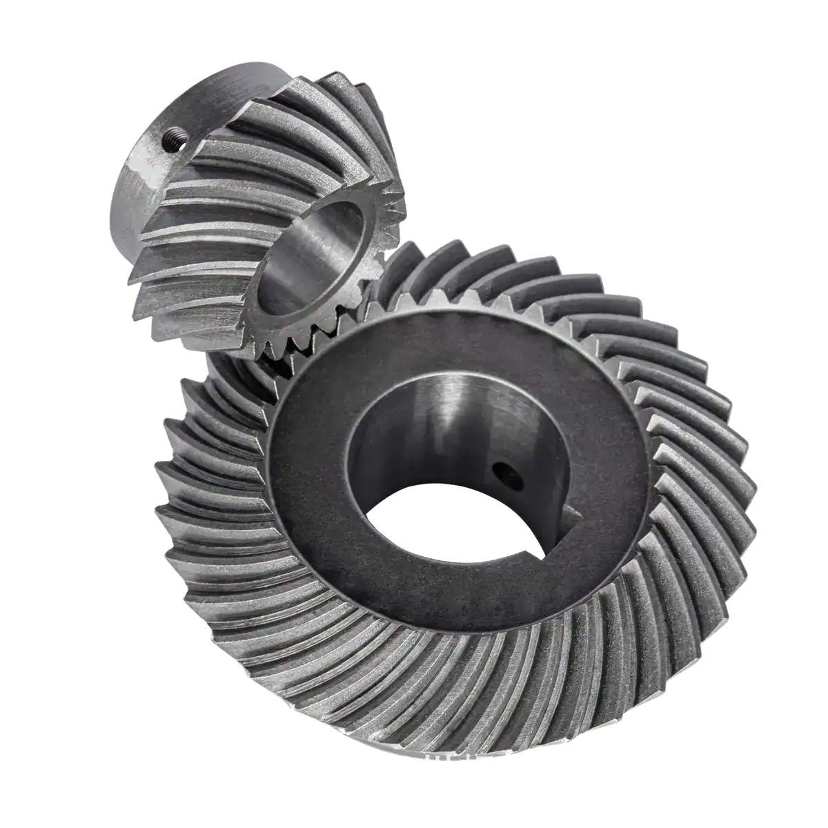
Spiral Bevel Gear
NOWARUN produces custom spiral bevel gears cut to the GLEASON or KLINGELNBERG system to match the exact driveline…
View specifications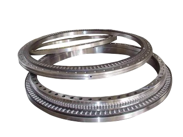
Slewing Ring
Slewing ring spur gears provide rotational drive and torque transmission for rotating machinery, cut to your print…
View specifications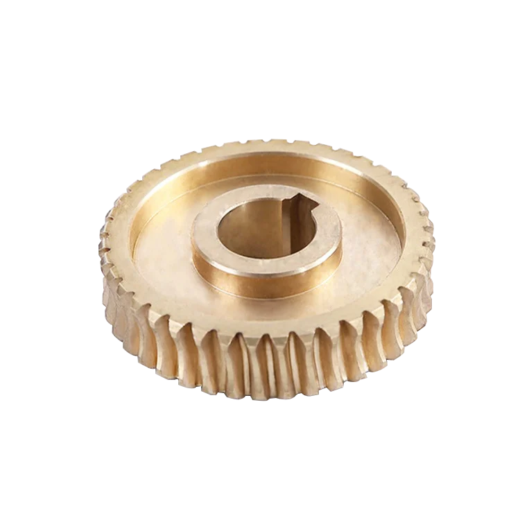
Worm Gear
Worm gears provide smooth speed reduction and high ratio torque transmission across perpendicular non-intersecting…
View specifications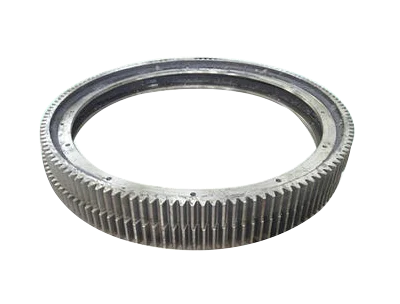
Gear Ring
Gear rings transmit torque in planetary gearboxes, slewing assemblies, and machine drives, cut to your print rather…
View specificationsQuote Crown Gear to Your Drawing
Send the print with the quantity, material, tolerance and surface treatment. Missing details get asked about, not assumed.