Two Distinct Tooling Geometries for Spiral Bevel Gears
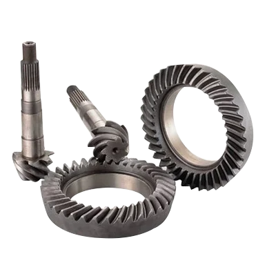
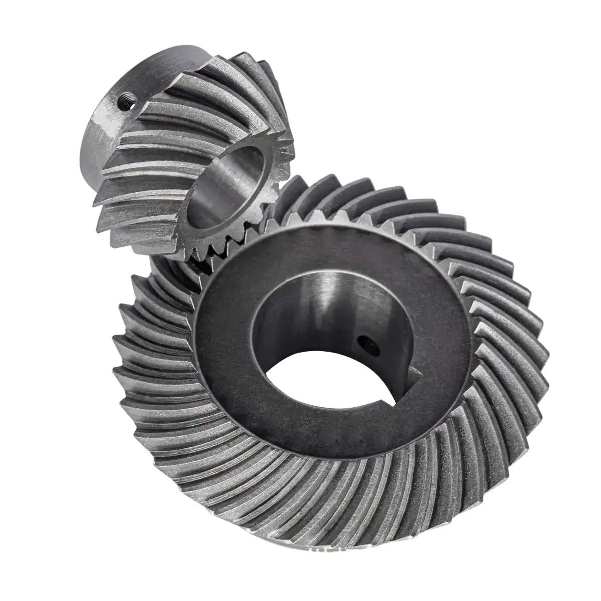
Spiral bevel gears are cut to either the GLEASON or KLINGELNBERG tooth system. The choice determines tooth geometry, flank curvature, and the specific cutter tooling required during production. Both systems handle heavy directional torque transfer in machinery drives, but their manufacturing setups and contact patterns follow distinct standards. NOWARUN processes custom spiral bevel gears under both GLEASON and KLINGELNBERG systems across a module range of 0.5 to 10.
Spiral Bevel Gear specifications
Milling Grinding and DIN Precision Levels
Spiral bevel gears in both systems are produced by milling and finishing via grinding. Precision levels range from DIN 3 for low-vibration, high-speed gearboxes down to DIN 7 for general machinery gear assemblies. Specifying the target DIN grade on your engineering drawing dictates the required grinding operation, directly affecting tooth runout, pitch consistency, and overall operational noise in the assembled drive.
Material Selection and Heat Treatment Steps
Tool system geometry fixes mesh dynamics, but flank fatigue life depends on metallurgy and heat treatment. NOWARUN machines GLEASON and KLINGELNBERG spiral bevel gears from carbon steel, alloy steel, polymer, and customized international grades. Core toughness and surface flank hardness are adjusted using carburizing, carbonitriding, quenching and tempering (QT), or induction hardening according to drawing load limits.
Drawing Callouts and Export Packaging
Procurement drawings should clearly define whether GLEASON or KLINGELNBERG geometry is required, along with the module, tooth count, heat treatment specification, and DIN 3 to DIN 7 tolerance band. Finished gears are protected against contact and corrosion during sea or air transport using PP bags, individual cartons, crates, or custom boxes matched to assembly line staging requirements.