
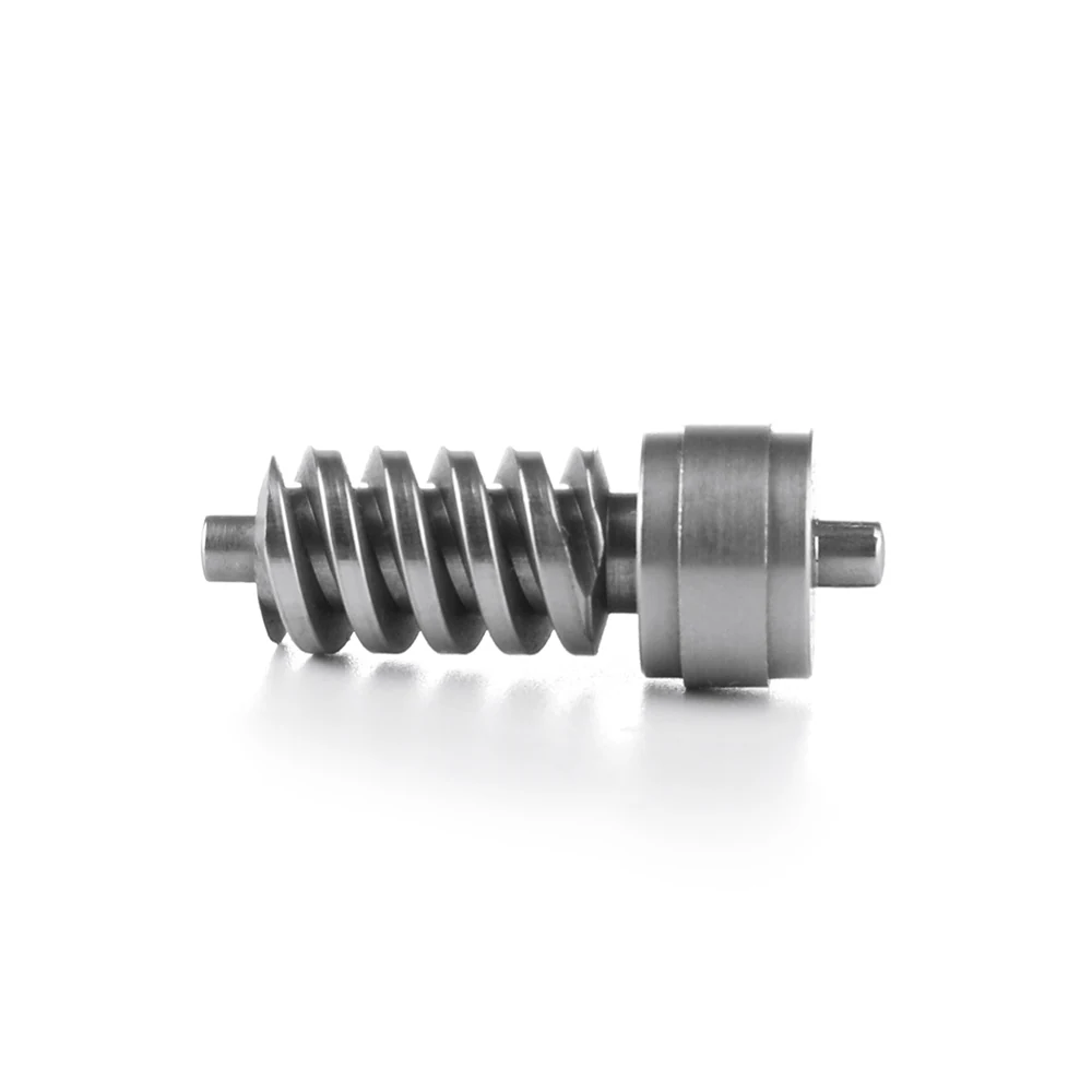
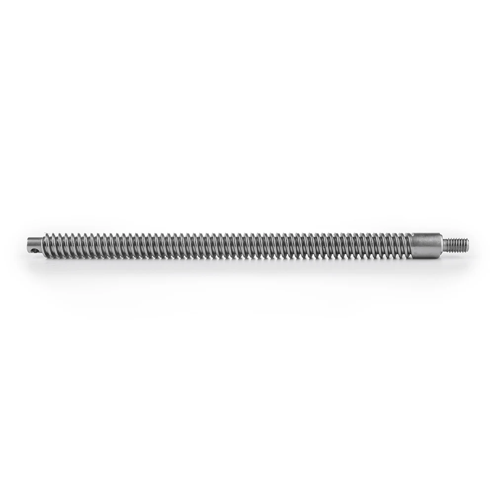
Machined Worm Gear Shaft
A worm cut on the same bar as its bearing seats, so the mesh does not depend on how well two parts were assembled
One Piece Instead Of A Worm Pressed Onto A Shaft
The worm form and the bearing journals are machined from a single bar. Nothing is pressed on, nothing is keyed, so there is no joint to slip under reversing load and no concentricity error between the worm and the seats that carry it.
Worm drives of this size appear in small gearboxes and adjusting mechanisms where a self-locking drive is wanted and space is tight.
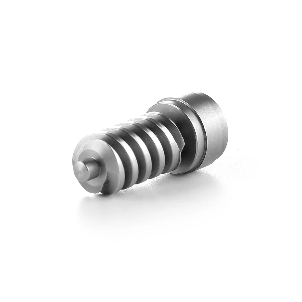
Why A One-Piece Worm Matters
No Slipping Joint
A pressed-on worm can move under reversing torque; an integral one cannot.
Mesh Set By The Machine
Worm-to-journal concentricity is a machining result rather than an assembly result.
Shorter Assembly
One part to handle, press and inspect instead of three.
Application Scenarios
- Small self-locking gearboxes
- Adjustment drives on machine guards and jigs
- Positioning mechanisms in automation equipment
- Hand-wheel drives on production tooling
Who It Is For
- Designers of compact self-locking drives
- Buyers replacing an assembled worm and shaft
- Service teams with worms that have worked loose in the field
- OEMs needing stainless worm drives
Failure Modes This Design Removes
- Pressed worms rotating on the shaft under reversing load
- Noise and wear from a worm running eccentric to its bearings
- Key ways that crack under shock loading
- Three part numbers where one would do
Integral Form
Worm and journals come from the same bar, in the same setup.
Mesh Checked
Where the wheel is supplied we verify the pair before shipping.
Material Choice
Stainless and case-hardened steel are both available routes.
Technical Features
- Worm thread form cut to the drawing
- Bearing journal each side of the worm
- Drive end machined for a pin, flat or spline
- Shoulder faces square to the shaft axis
- Deburred thread crests
Specifications
| Part Type | Integral worm gear shaft |
|---|---|
| Typical Material | Stainless steel or case-hardening steel |
| Primary Process | CNC turning, thread and form cutting |
| Mating Wheel | Supplied by customer or quoted separately |
| Tolerance | To customer drawing, confirmed at quotation |
| Heat Treatment | Subcontracted and managed by Shipu where specified |
| Inspection | Profile projector, mesh trial where the wheel is available |
| Sample Lead Time | Within 30 days of drawing approval |
Gear data comes from your drawing. We do not publish stock worm sizes because every one of these is a customer design.
Materials We Run
- SUS304 and SUS316L stainless for corrosion resistance
- Case-hardening steel where surface durability is the priority
- Free-cutting steel for light-duty adjusters
- Bronze wheels nominated by the customer for the mating gear
Manufacturing Process
Turn The Blank
Journals, shoulders and drive end are cut first.
Cut The Worm
The worm form is machined on the same centreline.
Heat Treat
Where specified, hardening is subcontracted and re-inspected on return.
Finish And Check
Journals are cleaned up and the mesh is trialled where possible.
Quality Control
- Worm form checked on a profile projector against the drawing
- Journal diameters and shoulder squareness measured
- Mesh trial with a customer wheel when one is supplied
- Hardness certificate retained when heat treatment is specified
- ISO 9001 system since 2009
Customization Options
- Worm lead, module and number of starts
- Journal sizes and retaining features
- Drive end form
- Heat treatment and surface finish
- Matched wheel sourced on request
Integral Worm Against Assembled Alternatives
| Worm pressed onto a shaft | No joint to slip and better concentricity, at a higher cost in material removed. |
|---|---|
| Plastic worm | Takes far more torque and temperature; a plastic worm is quieter and cheaper in light duty. |
| Ground worm | Grinding gives a finer finish for high-speed drives; machined worms suit the low-speed adjusting duty these parts do. |
Specifying A Worm Shaft
Give The Gear Data
Module, lead, starts and pressure angle, or the mating wheel drawing.
State The Duty
Torque, speed and reversing pattern drive the material choice.
Send The Wheel
If you can supply a wheel we will trial the mesh before shipping.
Decide On Hardening
Tell us the hardness and depth, and we will manage the treatment.
Machined Worm Gear Shaft — FAQ
Can you supply the mating worm wheel?
We can source or quote a wheel separately. If you supply one, we trial the mesh on sample parts before the batch ships, which catches centre-distance mistakes early.
Do you harden the worm?
Where the drawing calls for it, heat treatment is subcontracted to a qualified processor, managed by us, and the parts are re-inspected on return.
What worm data do you need to quote?
Module, lead, number of starts and pressure angle, plus the journal sizes. If you have the wheel drawing, send that too; it tells us the centre distance you are working to.
Is stainless suitable for a worm?
For light-duty adjusting drives, yes, and it is often chosen where corrosion matters more than wear. For continuous power transmission a case-hardened steel worm will last longer.
Can you copy an existing worm shaft?
We can measure one and produce a drawing for your approval, but the result reflects a used part. We always confirm the data with you before cutting.
Related Products
Related Guides
Send The Worm Data
Give us the gear data and the duty. We come back with material options, a price and a note on whether hardening is worth the cost for your application.