
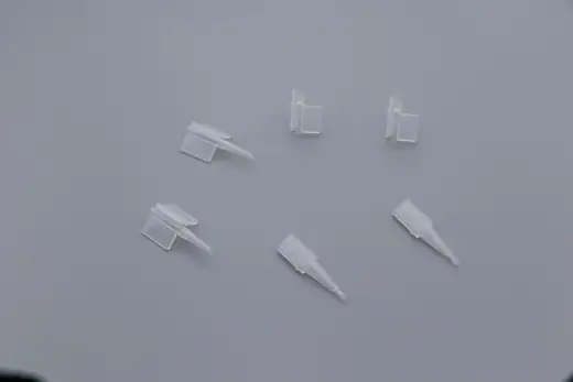
Luer Fittings And Connectors
Luer Connectors And Tips
A family of molded luer connectors, clamps and tips for fluid lines in infusion, sampling and instrument plumbing.
View Component →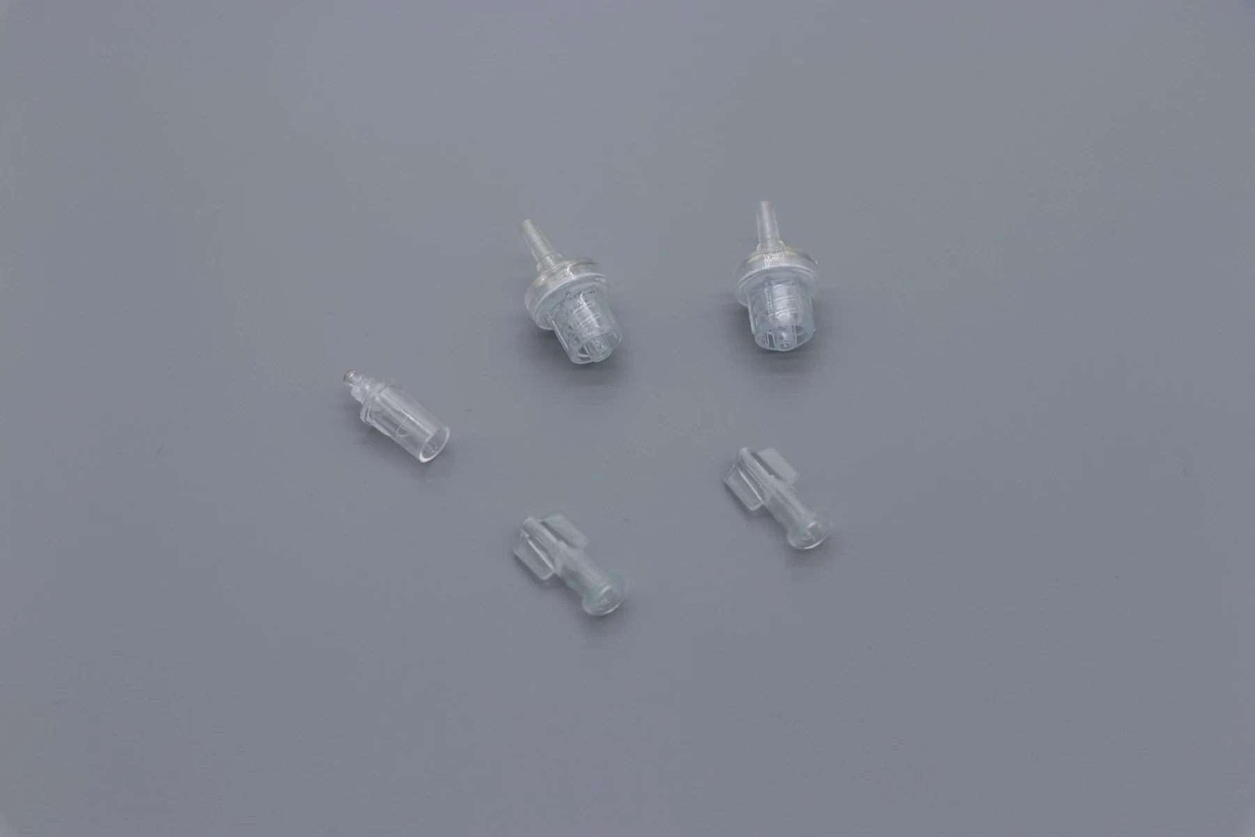
The design decisions on tiny components that are cheap to change in CAD and expensive to change in steel.
On a luer taper, a sealing land or an ophthalmic delivery path, a parting line in the wrong place is a functional defect rather than a cosmetic one. Decide its position while the part is still in CAD, because in steel it is a new cavity.
Uneven walls cool unevenly and warp, and on clear parts they also change how light passes through. Even sections matter more on small parts than on large ones, because there is no surrounding structure to hold the shape.
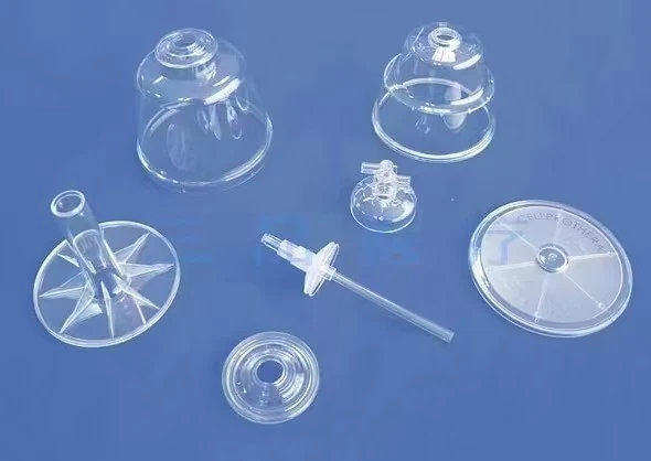
A part that cannot be ejected without deforming has no production future, however well it performs in testing. Ejector positions need to be on non functional surfaces, which constrains where features can sit.
The most useful thing on a drawing is a note saying which dimensions are functional. It lets the tool room put the accuracy where it matters and the tolerance where it does not, and it usually makes the tool cheaper rather than more expensive.
Before design freeze. Most of the changes we suggest cost nothing in CAD and cost a new cavity once the steel is cut.
Yes, with the specific reason and a suggested change. A quotation that hides a known problem only moves the cost later.
A family of molded luer connectors, clamps and tips for fluid lines in infusion, sampling and instrument plumbing.
View Component →
Very small molded fittings and adapters for compact fluidic assemblies where a standard luer body will not physically fit.
View Component →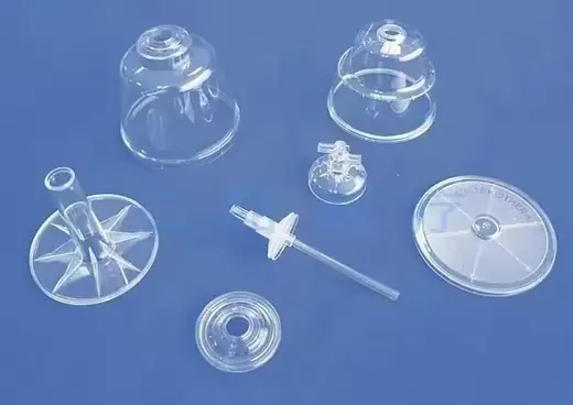
Molded blood separator bodies, discs and internals, carried over from the original product catalogue.
View Component →Thin clear sections warp as they cool, and a separator has to stay both dimensionally stable and optically clear across every cavity of every part in the assembly.
Read The Case →
Single use delivery and access devices where the tool, not the moulding machine, decides whether the device works.
See Applications →Getting from a first sampled part to a repeatable production lot without changing supplier halfway.
See The Stages →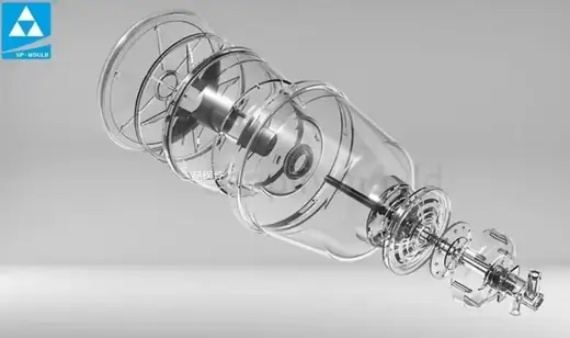
From your 3D part data to a sampled, released production tool, without the part leaving our site.
See The Stages →Send the drawing and we will apply exactly what this guide describes to your geometry, and tell you where it will not work.