Geometry and Precision Bands in Worm Drives
A worm drive pairs a threaded worm with a mating gear wheel to manage high ratio reductions in a compact envelope. Gear geometry dictates meshing behavior and efficiency across the drive. NOWARUN manufactures custom worm gearing across module 0.5 to 10, controlling tooth accuracy between DIN 5 and DIN 10 depending on whether the application requires commercial hobbing or finish grinding.
Material Selection for Worm Gear Flanks
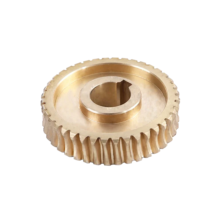
Worm gear sets rely on continuous sliding contact, which makes pair material selection critical for avoiding galling under load. Worm wheels are typically produced in bronze, brass, copper or custom alloys, running against carbon or alloy steel worms. Specifying the correct non-ferrous bronze or copper grade on the drawing ensures the gear wears smoothly rather than seizing during steady operation.
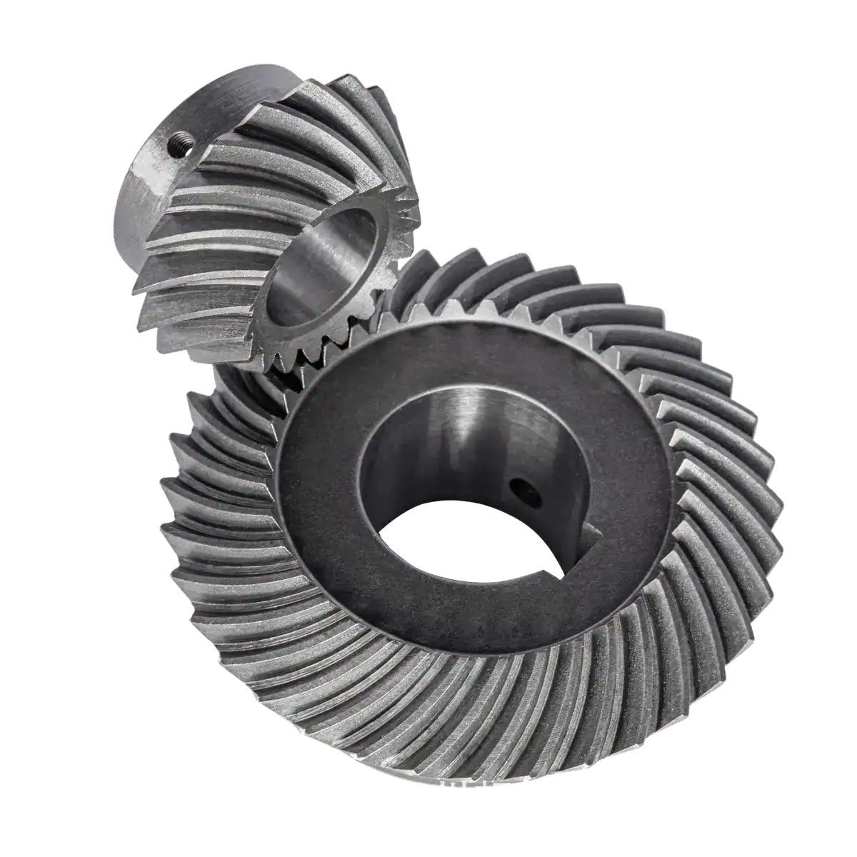
Spiral Bevel Gear specifications
Manufacturing Operations from Hobbing to Grinding
Cutting worm gears begins with precision hobbing and progresses to grinding when tighter contact patterns or finer DIN grades are needed. For high-speed worm drives, post-cut grinding maintains consistent lead error and tooth spacing within the module 0.5 to 10 range. Leaving the finishing requirements explicit avoids rough flank meshes that create excess heat in heavy-duty machinery.
Treatments and Drawing Specifications
While non-ferrous worm wheels focus on material composition, mating worms require hardened flank surfaces to endure sliding friction. Heat treatments like carburizing, carbonitriding, induction hardening, quenching or tempering are designated alongside surface treatments according to your drawing. Specifying the full treatment profile ensures the drive retains its tooth profile and mechanical hold under continuous load.