
Thermostat Terminals Explained
Most call backs on a thermostat swap trace to one mis-landed conductor. This is what each letter on a 24V sub-base does.
R, RH and RC
R is the 24V supply from the transformer. Where a system uses two transformers, one for heating and one for cooling, RH and RC are separate and the jumper between them must be removed. The S725 carries both.
W and Y
W calls the heating stage, Y calls the compressor for cooling. Second stages appear as W2 and Y2 on multi stage controls such as STN615 and model 3105.
G and C
G drives the indoor fan. C is the common conductor, and it is what allows a 24V thermostat to run without batteries. A missing C wire is the usual reason a retrofit stalls.
B and O
These drive a heat pump reversing valve. B energises in heating, O energises in cooling. Our heat pump models provide both as separate terminals so either convention wires directly.
E
Emergency heat. Where the specification calls for a dedicated emergency heat position rather than staged auxiliary heat, the S725 provides an E terminal.
Before you energise
Isolate the control circuit, photograph the existing wiring, and check that the combined load stays within 1.5 amp across all terminals on the 24V models.
Questions On This Topic
What if there is no C wire?
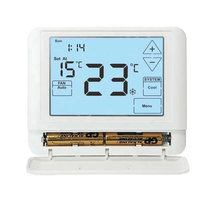
Use a battery powered model. Most of our 24V range runs from 2 x AAA alkaline cells as an alternative to hardwiring.
Do I remove the RH to RC jumper?
Only on systems with two separate transformers. On a single transformer system the jumper stays in place.
Can I use a conventional stat on a heat pump?
No. A conventional control has no reversing valve output, so the system will heat and cool in the wrong seasons.
Need This Checked Against Your System?
Send the equipment details on WhatsApp and we will confirm which of our models matches before you order.