
Terminals
Insulated piggy back terminals MDD,FDD,PBDD type
Insulated piggy back terminals are also namd splice crimp terminals or quick splice.Crimp terminals used to terminate stranded wires.
- Description of Insulated piggy back terminals Insulated piggy back terminals are also namd splice crimp terminals or quick splice.Crimp terminals
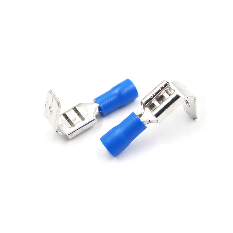
Overview
Insulated Piggy Back Terminals MDD,FDD,PBDD Type Description
Description of Insulated Piggy Back Terminals
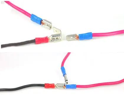
Insulated piggy back terminals are also namd splice crimp terminals or quick splice.Crimp terminals used to terminate stranded wires,creating a quality,reliable connection by ensuring each wire strand conducts current when properly crimped.Piggy back terminals especially useful when multiple reconnections could be necessary within terminal blocks or other similar devices. No breakage of wire strands when wire is bent, under stress or in a vibration environment. Twin ferrule designs allow two individual stranded conductors to be connected to the same termination,most beneficial in jumpering or other similar applications.
Material of Crimp Terminals
Tin plated copper,PVC
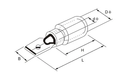
Parameters Table of MDD Type Splice Crimp Terminals
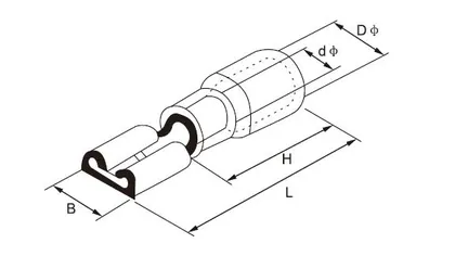
Parameters Table of FDD Type Crimp Terminals
Parameters Table of PBDD Type Piggy Back Terminals
Related Product
Features of Piggy Back Terminals
1.Smooth funnel entry to make wire insertion easier 2.Secure contacting even after multiple reconnections 3.Long-term contact resistance 4.No fraying of strands 5.No breakage of wire strands when wire is bent,under stress or in vibration environment
Specifications
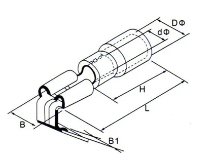
Codes Ranges and Dimensions
Figures below are reproduced from the CROP catalogue for this item.
| Item No. | Name Tab (mm) | Material thickness (mm) | Dimension(mm) | Colour | Specification | ||||
|---|---|---|---|---|---|---|---|---|---|
| B | D | d | L | H | |||||
| MDD 1.25-110(5) | 0.5X2.8 | 0.5 | 2.8 | 4.3 | 1.7 | 17.7 | 10.0 | Red | Conductor section:0.5-1.5mm2 A.W.G.: 22-16 Max Current:I max.=10A |
| MDD 1.25-110(8) | 0.8X2.8 | 0.8 | 2.8 | 17.7 | |||||
| MDD 1.25-187(5) | 0.5X4.75 | 0.5 | 4.75 | 20.0 | |||||
| MDD 1.25-187(8) | 0.8X4.75 | 0.8 | 4.75 | 20.0 | |||||
| MDD 1.25-250 | 0.8X6.35 | 0.4 | 6.35 | 21.0 | |||||
| MDD 2-110(5) | 0.5X2.8 | 0.5 | 2.8 | 4.3 | 2.3 | 17.7 | 10.0 | Blue | Conductor section:1.5-2.5mm2 A.W.G.: 16-14 Max Current:I max.=15A |
| MDD 2-110(8) | 0.8X2.8 | 0.8 | 2.8 | 17.7 | |||||
| MDD 2-187(5) | 0.5X4.75 | 0.5 | 4.75 | 20.0 | |||||
| MDD 2-187(8) | 0.8X4.75 | 0.8 | 4.75 | 20.0 | |||||
| MDD 2-250 | 0.8X6.35 | 0.4 | 6.35 | 21.0 | |||||
| MDD 5.5-187 | 0.5X4.75 | 0.5 | 4.75 | 5.7 | 3.4 | 23.0 | 13.0 | Yellow | Conductor section:4-6mm2 A.W.G.: 12-10 Max Current:I max.=24A |
| MDD 5.5-250 | 0.8X6.35 | 0.4 | 6.35 | 25.0 |
| Item No. | Name Tab (mm) | Material thickness (mm) | Dimension(mm) | Colour | Specification | ||||
|---|---|---|---|---|---|---|---|---|---|
| B | D | d | L | H | |||||
| FDD 1.25-110(5) | 0.5X2.8 | 0.3 | 3.8 | 3.8 | 1.7 | 19.0 | 10.0 | Red | Conductor section:0.5-1.5mm2 A.W.G.: 22-16 Max Current:I max.=19A |
| FDD 1.25-110(8) | 0.8X2.8 | 0.3 | 3.8 | 19.0 | |||||
| FDD 1.25-187(5) | 0.5X4.75 | 0.35 | 5.6 | 19.0 | |||||
| FDD 1.25-187(8) | 0.8X4.75 | 0.35 | 5.6 | 19.0 | |||||
| FDD 1.25-205 | 0.5X5.2 | 0.35 | 6.5 | 20.0 | |||||
| FDD 1.25-250 | 0.8X6.35 | 0.4 | 7.4 | 21.0 | |||||
| FDD 2-110(5) | 0.5X2.8 | 0.3 | 3.8 | 4.3 | 2.3 | 19.0 | 10.0 | Blue | Conductor section:1.5-2.5mm2 A.W.G.: 16-14 Max Current:I max.=15A |
| FDD 2-110(8) | 0.8X2.8 | 0.3 | 3.8 | 19.0 | |||||
| FDD 2-187(5) | 0.5X4.75 | 0.35 | 5.6 | 19.0 | |||||
| FDD 2-187(8) | 0.8X4.75 | 0.35 | 5.6 | 19.0 | |||||
| FDD 2-205 | 0.5X5.2 | 0.35 | 6.5 | 20.0 | |||||
| FDD 2-250 | 0.8X6.35 | 0.4 | 7.4 | 21.0 | |||||
| FDD 2-312 | 0.8X8.0 | 0.4 | 9.0 | 23.0 | |||||
| FDD 5.5-187 | 0.5X4.75 | 0.4 | 5.6 | 3.4 | 5.7 | 23.0 | 14.0 | Yellow | Conductor section:4-6mm2 A.W.G.: 12-10 Max Current:I max.=24A |
| FDD 5.5-250 | 0.8X6.35 | 0.4 | 7.4 | 25.0 | |||||
| FDD 5.5-312 | 0.8X8.0 | 0.5 | 9.0 | 27.0 | |||||
| FDD 5.5-375 | 1.2×9.4 | 0.5 | 10.9 | 29.6 |
| Item No. | Name Tab (mm) | Material thickness (mm) | Dimension(mm) | Colour | Specification | |||||
|---|---|---|---|---|---|---|---|---|---|---|
| B | B1 | D | d | L | H | |||||
| PBDD 1.25-250 | 0.8X6.35 | 0.4 | 7.4 | 6.35 | 3.8 | 1.7 | 21.5 | 10.0 | Red | Conductor section:0.5-1.5mm2 A.W.G.: 22-16 Max Current:I max.=10A |
| PBDD 2-250 | 0.8X6.35 | 0.4 | 7.4 | 6.35 | 4.3 | 2.3 | 21.5 | 10.0 | Blue | Conductor section:1.5-2.5mm2 A.W.G.: 16-14 Max Current:I max.=15A |
| PBDD 5.5-250 | 0.8X6.35 | 0.4 | 7.4 | 6.3 | 5.7 | 3.4 | 25.0 | 13.0 | Yellow | Conductor section:4-6mm2 A.W.G.: 12-10 Max Current:I max.=24A |
Product Images
Ordering and Support
From Enquiry To Delivered Order
Send The Requirement
Item code, conductor or cable size and quantity, or a drawing and a photograph for a non standard part.
Quotation
Price, packing, carton quantity and lead time are confirmed against the catalogue reference.
Sample or Tooling
Samples are sent for approval. Parts that need a new mould go through the in house mould division.
Production and Shipment
Production to IEC and GB standards, then packing and shipment on the agreed terms.
Answers
Frequently Asked Questions
How do I choose the right size?
Is Insulated piggy back terminals MDD,FDD,PBDD type available as a sample before a production order?
Which standards do CROP products follow?
Can items be produced to our own drawing?
How do I obtain the PDF catalogue?
Related
Other Items In Terminals
 Bootlace ferrule DBN type
Terminals
Bootlace ferrule DBN type
Terminals
 Bullet quick splice wire terminals FRD&MPD type
Terminals
Bullet quick splice wire terminals FRD&MPD type
Terminals
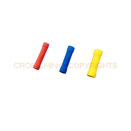 Butt splice BV type
Terminals
Butt splice BV type
Terminals
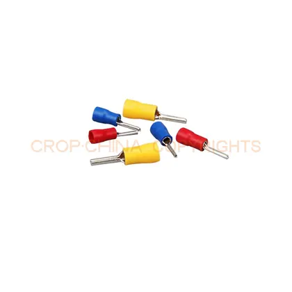 Core end terminal PTV type
Terminals
Core end terminal PTV type
Terminals
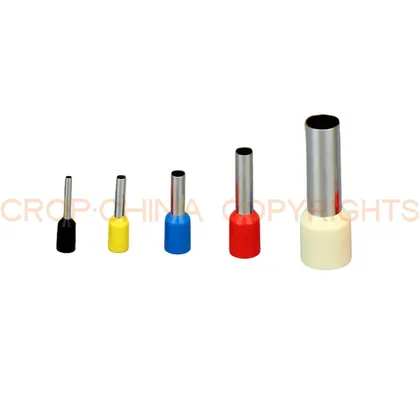 Crimp ferrule pin length E type
Terminals
Crimp ferrule pin length E type
Terminals
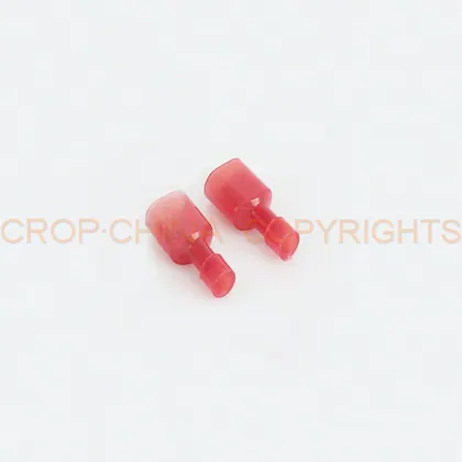 Electrical wire crimp connector FDFN&MDFN type
Terminals
Electrical wire crimp connector FDFN&MDFN type
Terminals
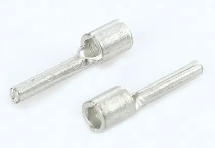 Electrical wire terminal PTN type
Terminals
Electrical wire terminal PTN type
Terminals
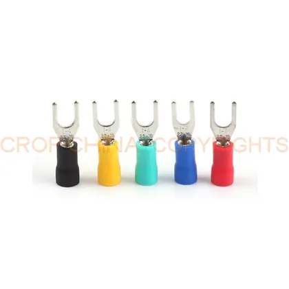 Fork spade crimp terminal SV type
Terminals
Fork spade crimp terminal SV type
Terminals
Next Step
Get A Price For Insulated piggy back terminals MDD,FDD,PBDD type
Send the code, the size and the quantity. Drawings for non standard versions are welcome.